
Research, Development, and Technology
Turner-Fairbank Highway Research Center
6300 Georgetown Pike
McLean, VA 22101-2296
Evaluation of Pedestrian Hybrid Beacons
and Rapid Flashing Beacons
PUBLICATION NO. FHWA-HRT-16-040 JULY 2016

FOREWORD
The overall goal of the Federal Highway Administration’s (FHWA) Pedestrian and Bicycle
Safety Research Program is to improve safety and mobility for pedestrians and bicyclists.
The program strives to make it safer and easier for pedestrians, bicyclists, and drivers to share
roadways through the development of safer crosswalks, sidewalks, and pedestrian technologies
as well as through the expansion of educational and safety programs.
This report documents an FHWA project that includes four studies that investigated how
characteristics of rectangular rapid-flashing beacons (RRFBs) and pedestrian hybrid beacons
(PHBs) affected the likelihood of drivers yielding to a pedestrian. The results of this project
supported the development of two Manual on Uniform Traffic Control Devices official
interpretations for the RRFB: Official Interpretation #4(09)-41 (I)—Additional Flash Pattern for
RRFBs and Official Interpretation #4(09)-58 (I)—Placement of RRFB Units Above Sign.
(1–3)
The
overall 96 percent high yielding for PHBs identified in this research, along with findings from
previous studies, support the use of this device at a variety of locations, such as on high-speed
roads, wide roads, and at residential intersections.
This report should be of interest to engineers, planners, and other community authorities who
share an interest in safeguarding the lives of roadway users, especially pedestrians.
Monique R. Evans
Director, Office of Safety
Research and Development
Notice
This document is disseminated under the sponsorship of the U.S. Department of Transportation
in the interest of information exchange. The U.S. Government assumes no liability for the use of
the information contained in this document. This report does not constitute a standard,
specification, or regulation.
The U.S. Government does not endorse products or manufacturers. Trademarks or
manufacturers' names appear in this report only because they are considered essential to the
objective of the document.
Quality Assurance Statement
The Federal Highway Administration (FHWA) provides high-quality information to serve
Government, industry, and the public in a manner that promotes public understanding. Standards
and policies are used to ensure and maximize the quality, objectivity, utility, and integrity of its
information. FHWA periodically reviews quality issues and adjusts its programs and processes to
ensure continuous quality improvement.

TECHNICAL REPORT DOCUMENTATION PAGE
1. Report No.
FHWA-HRT-16-040
2. Government Accession No.
3. Recipient’s Catalog No.
4. Title and Subtitle
Evaluation of Pedestrian Hybrid Beacons and Rapid Flashing Beacons
5. Report Date
July 2016
6. Performing Organization Code
7. Author(s)
Kay Fitzpatrick, Raul Avelar, Michael Pratt, Marcus Brewer,
James Robertson, Tomas Lindheimer, and Jeff Miles
8. Performing Organization Report No.
9. Performing Organization Name and Address
Texas Transportation Institute
The Texas A&M University System
College Station, TX 77843-3135
10. Work Unit No. (TRAIS)
11. Contract or Grant No.
DTFH61-08-D-00032, Task Order #8
12. Sponsoring Agency Name and Address
Office of Safety Research and Development
Federal Highway Administration
6300 Georgetown Pike
McLean, VA 22101-2296
13. Type of Report and Period Covered
Technical Report:
October 2012–March 2016
14. Sponsoring Agency Code
15. Supplementary Notes
The Contracting Officer’s Technical Representative was Ann Do, HRDS-30.
16. Abstract
Two pedestrian treatments receiving national attention are the rectangular rapid-flashing beacon (RRFB) and the
pedestrian hybrid beacon (PHB). These devices have unique characteristics that produce improved vehicle stopping
and yielding to crossing pedestrians. This Federal Highway Administration (FHWA) project includes multiple
studies to help refine these devices. A closed-course RRFB study measured the time to determine the position and
direction of a cutout representation of a pedestrian on a crosswalk to identify conditions that produced faster and
more accurate recognition. Placing the beacons above rather than below the warning sign produced better
recognition. A following open-road study investigated driver yielding when the beacons were located above and
below the warning sign at 13 sites. Results indicated that any differences between the above and below positions
were minor and statistically insignificant. With the apparent benefits identified from the closed-course study
(i.e., lower discomfort and improved ability to detect the pedestrian) and the lack of difference in driver yielding,
locating the beacons above the sign could improve the overall effectiveness of this treatment. FHWA issued an
official interpretation in early 2016 to permit the placement of the beacons above the sign.
(3)
An open-road study was
also conducted to determine driver yielding for different RRFB flash patterns at eight sites, seven of which were
four-lane crossings with 40- or 45-mi/h speed limits. The patterns selected for evaluation were the 2-5 flash pattern
(two flashes on one side followed by five flashes on other side) that was currently in use, a pattern using a
combination of wig-wag and simultaneous (WW+S) flashes, and a pattern using a combination of long and short
flashes called “blocks.” The statistical analysis showed no statistical significant difference between patterns; in other
words, the newer patterns were as effective as the 2-5 flash pattern. As a result, FHWA issued an official
interpretation indicating the preference for the WW+S pattern.
(2)
In the final study, behaviors at PHBs were
investigated. The PHB has shown great potential in improving safety and driver yielding; however, questions have
been asked regarding actual driver and pedestrian behavior. For the 20 PHB sites in the open-road study, driver
yielding to pedestrians averaged 96 percent. Overall, 91 percent of the pedestrians pushed the pushbutton to activate
the PHB in the crosswalk. A greater percentage number of pedestrians activated the device when on 45-mi/h posted
speed limit roads as compared to roads with posted speed limits of 40 mi/h or less.
17. Key Words
Rectangular rapid-flashing beacon, Pedestrian hybrid
beacon, RRFB, PHB, Pedestrian crossing, Driver
yielding to pedestrians, Pedestrian crosswalk
18. Distribution Statement
No restrictions. This document is available to the public
through the National Technical Information Service,
Springfield, VA 22161.
http://www.ntis.gov
19. Security Classif.(of this report)
Unclassified
20. Security Classif.(of this page)
Unclassified
21. No. of Pages
165
22. Price
Form DOT F 1700.7 (8-72) Reproduction of completed page authorized.

ii
SI* (MODERN METRIC) CONVERSION FACTORS
APPROXIMATE CONVERSIONS TO SI UNITS
Symbol When You Know Multiply By To Find Symbol
LENGTH
in inches 25.4 millimeters mm
ft feet 0.305 meters m
yd yards 0.914 meters m
mi miles 1.61 kilometers km
AREA
in
2
square inches 645.2 square millimeters mm
2
ft
2
square feet 0.093 square meters m
2
yd
2
square yard 0.836 square meters m
2
ac acres 0.405 hectares ha
mi
2
square miles 2.59 square kilometers km
2
VOLUME
fl oz fluid ounces 29.57 milliliters mL
gal gallons 3.785 liters L
ft
3
cubic feet 0.028 cubic meters m
3
yd
3
cubic yards 0.765 cubic meters m
3
NOTE: volumes greater than 1000 L shall be shown in m
3
MASS
oz ounces 28.35 grams g
lb pounds 0.454 kilograms kg
T short tons (2000 lb) 0.907 megagrams (or "metric ton") Mg (or "t")
TEMPERATURE (exact degrees)
o
F Fahrenheit 5 (F-32)/9 Celsius
o
C
or (F-32)/1.8
ILLUMINATION
fc foot-candles 10.76 lux lx
fl foot-Lamberts 3.426 candela/m
2
cd/m
2
FORCE and PRESSURE or STRESS
lbf poundforce 4.45 newtons N
lbf/in
2
poundforce per square inch 6.89 kilopascals kPa
APPROXIMATE CONVERSIONS FROM SI UNITS
Symbol When You Know Multiply By To Find Symbol
LENGTH
mm millimeters 0.039 inches in
m meters 3.28 feet ft
m meters 1.09 yards yd
km kilometers 0.621 miles mi
AREA
mm
2
square millimeters 0.0016 square inches in
2
m
2
square meters 10.764 square feet ft
2
m
2
square meters 1.195 square yards yd
2
ha hectares 2.47 acres ac
km
2
square kilometers 0.386 square miles mi
2
VOLUME
mL milliliters 0.034 fluid ounces fl oz
L liters 0.264 gallons gal
m
3
cubic meters 35.314 cubic feet ft
3
m
3
cubic meters 1.307 cubic yards yd
3
MASS
g grams 0.035 ounces oz
kg kilograms 2.202 pounds lb
Mg (or "t") megagrams (or "metric ton") 1.103 short tons (2000 lb) T
TEMPERATURE (exact degrees)
o
C Celsius 1.8C+32 Fahrenheit
o
F
ILLUMINATION
lx lux 0.0929 foot-candles fc
cd/m
2
candela/m
2
0.2919 foot-Lamberts fl
FORCE and PRESSURE or STRESS
N newtons 0.225 poundforce lbf
kPa kilopascals 0.145 poundforce per square inch lbf/in
2
*SI is the symbol for th International System of Units. Appropriate rounding should be made to comply with Section 4 of ASTM E380. e
(Revised March 2003
)
iii
TABLE OF CONTENTS
CHAPTER 1. INTRODUCTION ................................................................................................ 1
BACKGROUND ..................................................................................................................... 1
STUDY OBJECTIVE ............................................................................................................. 1
Impact of Rapid-Flashing Yellow Light-Emitting Diodes (LEDs) on Detecting
Pedestrians in a Closed-Course Setting .............................................................................. 1
Driver-Yielding Results for Beacons Placed Above or Below Crossing Sign in an
Open-Road Setting .............................................................................................................. 2
Driver-Yielding Results for Three Rectangular Rapid-Flash Patterns in an
Open-Road Setting .............................................................................................................. 2
PHB Study .......................................................................................................................... 2
APPROACH ............................................................................................................................ 2
REPORT ORGANIZATION ................................................................................................. 3
CHAPTER 2. LITERATURE REVIEW .................................................................................... 5
FHWA INTERIM APPROVAL OF RRFBS ....................................................................... 5
FHWA OFFICIAL INTERPRETATIONS .......................................................................... 5
RRFB ........................................................................................................................................ 7
PHB .......................................................................................................................................... 8
MULTIPLE PEDESTRIAN TREATMENTS ................................................................... 10
CHAPTER 3. IMPACT OF RAPID-FLASHING YELLOW LEDS ON DETECTING
PEDESTRIANS IN A CLOSED-COURSE SETTING ..................................................... 11
INTRODUCTION................................................................................................................. 11
Study Objective ................................................................................................................. 12
Overview of Study Approach ........................................................................................... 12
COURSE DEVELOPMENT ............................................................................................... 13
Riverside Campus ............................................................................................................. 13
Pedestrian Crossing Assemblies Selected for Study ......................................................... 13
Study Site .......................................................................................................................... 14
Cutout Pedestrian .............................................................................................................. 16
Flash Pattern for Assemblies ............................................................................................ 18
Brightness of LEDs ........................................................................................................... 21
Combinations Studied ....................................................................................................... 23
Concluding Survey............................................................................................................ 26
DATA COLLECTION ......................................................................................................... 31
Study Periods .................................................................................................................... 31
Participants ........................................................................................................................ 31
Participant’s Tasks ............................................................................................................ 32
Instrumented Vehicle ........................................................................................................ 32
Participant Intake .............................................................................................................. 33
Initial Button Push Training.............................................................................................. 34
Vehicle Review ................................................................................................................. 35
Data Collection at Study Site ............................................................................................ 35
iv
DATA REDUCTION ............................................................................................................ 36
Participant Demographics ................................................................................................. 36
Data Cleaning.................................................................................................................... 37
Responses .......................................................................................................................... 37
Box Plots ........................................................................................................................... 38
Mosaic Plots ...................................................................................................................... 39
Potential Outliers .............................................................................................................. 39
FINDINGS ............................................................................................................................. 40
Detection Time to Correctly Identify Pedestrian Walking Direction ............................... 40
Accuracy of Detecting Pedestrian Direction..................................................................... 46
Discomfort ........................................................................................................................ 53
Concluding Survey............................................................................................................ 57
STATISTICAL ANALYSIS ............................................................................................ 61
Pedestrian Detection Time ................................................................................................ 61
Accuracy of Detecting Pedestrian Direction..................................................................... 68
Discomfort Glare .............................................................................................................. 77
CHAPTER 4. DRIVER-YIELDING RESULTS FOR BEACONS PLACED ABOVE
OR BELOW CROSSING SIGN IN AN OPEN-ROAD SETTING.................................. 87
INTRODUCTION................................................................................................................. 87
Study Overview ................................................................................................................ 87
Study Objective ................................................................................................................. 87
STUDY DEVELOPMENT ................................................................................................... 87
Study Sites ........................................................................................................................ 87
Study Assemblies .............................................................................................................. 90
Rotation ............................................................................................................................. 91
DATA COLLECTION AND REDUCTION ...................................................................... 91
Study Periods .................................................................................................................... 91
Staged Pedestrian Protocol ............................................................................................... 92
Driver Yielding ................................................................................................................. 93
RESULTS .............................................................................................................................. 94
COMPARISON OF BELOW TO ABOVE ........................................................................ 95
CHAPTER 5. DRIVER-YIELDING RESULTS FOR THREE RRFB PATTERNS
IN AN OPEN-ROAD SETTING ......................................................................................... 97
INTRODUCTION................................................................................................................. 97
Study Overview ................................................................................................................ 97
Study Objective ................................................................................................................. 97
STUDY DEVELOPMENT ................................................................................................... 97
Study Sites ........................................................................................................................ 97
Temporary Light Bar ........................................................................................................ 98
Flash Patterns .................................................................................................................... 99
Brightness of LEDs ......................................................................................................... 102
Sample Size ..................................................................................................................... 102
Flash Pattern Order ......................................................................................................... 102
DATA COLLECTION AND REDUCTION .................................................................... 103
Study Periods .................................................................................................................. 103
Staged Pedestrian Protocol ............................................................................................. 103
v
DATA REDUCTION .......................................................................................................... 103
RESULTS ............................................................................................................................ 104
Patterns Used with Temporary Light Bars...................................................................... 104
2-5 Flash Pattern ............................................................................................................. 106
CHAPTER 6. PHB STUDY ..................................................................................................... 107
INTRODUCTION............................................................................................................... 107
Study Objective ............................................................................................................... 109
STUDY SITES ..................................................................................................................... 109
DATA COLLECTION AND REDUCTION .................................................................... 113
DRIVER BEHAVIOR FINDINGS ................................................................................... 114
Driver Behavior During Dark Indication ........................................................................ 114
Driver Position Relative to Pedestrian Position During Steady or Flashing Red
Indications When the Driver Drove Across the Crosswalk ............................................ 115
Driver Yielding Behavior During Steady or Flashing Red Indications .......................... 117
Driver Behavior During Flashing Red Indication ........................................................... 119
Impact of PHB Actuation on Minor Movement Drivers ................................................ 119
PEDESTRIAN BEHAVIORS FINDINGS ....................................................................... 126
Pedestrian Departures by Indication ............................................................................... 126
Pedestrian Actuation of the PHB .................................................................................... 127
CONFLICTS FINDINGS ................................................................................................... 130
CHAPTER 7. SUMMARY/CONCLUSIONS, DISCUSSION, AND FUTURE
RESEARCH NEEDS .......................................................................................................... 133
OVERVIEW ........................................................................................................................ 133
CLOSED-COURSE STUDY ............................................................................................. 133
Summary/Conclusions .................................................................................................... 133
Discussion ....................................................................................................................... 137
ABOVE-BELOW (OPEN-ROAD) STUDY ..................................................................... 138
Summary/Conclusion ...................................................................................................... 138
Discussion ....................................................................................................................... 139
FLASH PATTERN (OPEN-ROAD) STUDY ................................................................... 139
Summary/Conclusions .................................................................................................... 139
Discussion ....................................................................................................................... 140
PHB STUDY ........................................................................................................................ 141
Summary/Conclusions .................................................................................................... 141
Discussion ....................................................................................................................... 142
FUTURE RESEARCH NEEDS......................................................................................... 143
ACKNOWLEDGMENTS ........................................................................................................ 149
REFERENCES .......................................................................................................................... 151
vi
LIST OF FIGURES
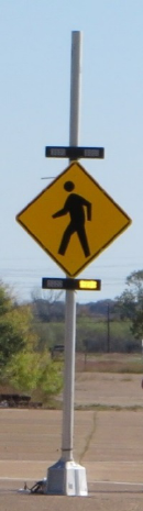
Figure 1. Photo. Study assembly containing LEDs above, below, and within the sign ............... 13
Figure 2. Illustration. Route for closed-course study .................................................................... 14
Figure 3. Illustration. Layout for the study site ............................................................................ 15
Figure 4. Photo. View of the study assemblies ............................................................................. 15
Figure 5. Photo. Back view of study site ...................................................................................... 16
Figure 6. Photo. View of 54-inch cutout pedestrian used in study ............................................... 17
Figure 7. Photo. Researcher removing short cutout pedestrian after placing tall cutout
pedestrian ...................................................................................................................................... 17
Figure 8. Illustration. Plan view showing pedestrian cutout positions ......................................... 18
Figure 9. Photo. View at start of the driving video for the concluding survey for
queries 1 and 2 .............................................................................................................................. 27
Figure 10. Photo. Training example with pedestrian facing left................................................... 34
Figure 11. Photo. Training example with pedestrian facing right ................................................ 34
Figure 12. Photo. Training example with no pedestrian ............................................................... 35
Figure 13. Illustration. Box plot details ........................................................................................ 38
Figure 14. Illustration. Mosaic plot details ................................................................................... 39
Figure 15. Graph. Daytime detection time by LED location and target intensity ........................ 44
Figure 16. Graph. Nighttime detection time by LED location and target intensity ...................... 45
Figure 17. Graph. Daytime detection time by pedestrian position and target intensity ................ 45
Figure 18. Graph. Nighttime detection time by pedestrian position and target intensity ............. 46
Figure 19. Graph. Daytime correct detection rate by target intensity ........................................... 50
Figure 20. Graph. Nighttime correct detection rate by target intensity ........................................ 50
Figure 21. Graph. Daytime correct detection rate by flash pattern ............................................... 51
Figure 22. Graph. Nighttime correct detection rate by flash pattern ............................................ 51
Figure 23. Graph. Daytime detection rate by age ......................................................................... 52
Figure 24. Graph. Nighttime detection rate by age ....................................................................... 52
Figure 25. Graph. Older driver daytime discomfort rating for set I ............................................. 53
Figure 26. Graph. Younger driver daytime discomfort rating for set I......................................... 54
Figure 27. Graph. Older driver nighttime discomfort rating for set I ........................................... 55
Figure 28. Graph. Younger driver nighttime discomfort rating for set I ...................................... 55
Figure 29. Graph. Older driver nighttime discomfort rating for set II .......................................... 56
Figure 30. Graph. Younger driver nighttime discomfort rating for set II ..................................... 56
Figure 31. Graph. Results for survey queries 1 and 2 ................................................................... 57
Figure 32. Graph. Number of pulses by percent of participants ................................................... 61
Figure 33. Equation. Natural logarithm of detection time ............................................................ 62
Figure 34. Equation. Accuracy analysis ....................................................................................... 69
Figure 35. Equation. Accuracy rate .............................................................................................. 69
Figure 36. Equation. Logit model ................................................................................................. 69
Figure 37. Equation. Odds ratio corresponding to levels A and B of factor X
i1
............................ 70
Figure 38. Graph. Daytime estimated accuracy rate by age and pedestrian position ................... 72
Figure 39. Graph. Close-up view of daytime estimated accuracy rate by age and
pedestrian position ........................................................................................................................ 73
Figure 40. Graph. Nighttime estimated accuracy rate by age and LED intensity ........................ 75
vii
Figure 41. Graph. Close-up view of nighttime estimated accuracy rate by age and
LED intensity ................................................................................................................................ 75
Figure 42. Graph. Idealized relationship between discrete and real discomfort scales ................ 78
Figure 43. Equation. Cumulative frequency ................................................................................. 79
Figure 44. Equation. Odds ratio for levels A and B of variable X
i1
at a maximum level of
discomfort ..................................................................................................................................... 79
Figure 45. Equation. Revised odds ratio ....................................................................................... 79
Figure 46. Graph. Estimated cumulative probabilities by age of participant for the discrete
scale of discomfort when using 2,200 candelas of intensity and the 2-5 flash pattern ................. 85
Figure 47. Photo. Example of RRFB placed above the sign ........................................................ 90
Figure 48. Photo. Example of RRFB placed below the sign ........................................................ 90
Figure 49. Equation. Driver yielding rate ..................................................................................... 93
Figure 50. Photo. Installation of the light bar in field ................................................................... 98
Figure 51. Photo. CS-02 study site with installed temporary light bars and staged
pedestrian crossing ........................................................................................................................ 99
Figure 52. Illustration. Flash patterns studied ............................................................................. 101
Figure 53. Photo. Example of PHB installation in Tucson, AZ ................................................. 107
Figure 54. Photo. Example of PHBs being used in Austin, TX.................................................. 108
Figure 55. Photo. Example of sign used in Tucson, AZ ............................................................. 111
Figure 56. Photo. Example of internally illuminated sign used in Tucson, AZ ......................... 112
Figure 57. Photo. Sign used in Austin, TX ................................................................................. 112
Figure 58. Photo. Sign recommended by FHWA to address comprehension issues with the
flashing red phase ....................................................................................................................... 113
Figure 59. Photo. Example of advance warning sign used in Tucson, AZ ................................. 113
Figure 60. Illustration. Pedestrian and driver positions when the pedestrian is on the initial
approach and vehicles are present on the same approach and on the other approach ................ 116
Figure 61. Illustration. Minor movements at a PHB-controlled crosswalk ................................ 120
Figure 62. Graph. Volume cumulative distribution when pedestrian started the crossing ......... 127
Figure 63. Graph. Percentage of pedestrians pushing the button, by posted speed limit ........... 129
Figure 64. Graph. Percentage of pedestrians pushing the button, by crossing distance ............. 129
Figure 65. Graph. Percentage of pedestrians pushing the button, by 1-min volume counts
adjusted to hourly counts ............................................................................................................ 129
viii
LIST OF TABLES
Table 1. Summary of RRFB official interpretations released prior to 2014 ................................... 6
Table 2. Summary of RRFB official interpretation developed using the results of this
research project ............................................................................................................................... 7
Table 3. Flash patterns used with LEDs located in rectangular beacons above or below
the sign .......................................................................................................................................... 19
Table 4. Flash patterns used with LEDs within sign .................................................................... 20
Table 5. LED characteristics for set I ........................................................................................... 22
Table 6. LED characteristics for set II .......................................................................................... 23
Table 7. Number of variable combinations tested during the closed-course study ...................... 25
Table 8. Video assignments and flash patterns for each query by participant group ................... 28
Table 9. Flash patterns for queries 1 and 2 showing moving videos from driver perspective ..... 29
Table 10. Flash patterns used for queries 3 and 4 with the video showing a close-up view ........ 30
Table 11. Distribution of participants ........................................................................................... 32
Table 12. Demographic information for participants ................................................................... 37
Table 13. Daytime average detection time for set I ...................................................................... 41
Table 14. Nighttime average detection time for set I .................................................................... 42
Table 15. Nighttime average detection time for set II and combined total for sets I and II ......... 43
Table 16. Daytime accuracy of correct detection for set I ............................................................ 47
Table 17. Nighttime accuracy of correct detection ....................................................................... 48
Table 18. Results for survey queries 1 and 2 ................................................................................ 57
Table 19. Percent of participants who felt a sense of urgency to yield for signs with
no active LEDs and LEDs below the sign .................................................................................... 59
Table 20. Percent of participant results for sense of urgency to yield for LEDs above
the sign .......................................................................................................................................... 60
Table 21. Number of pulses on light bar ....................................................................................... 61
Table 22. Daytime ANOVA for detection time fixed effects ....................................................... 63
Table 23. Daytime detection time fixed effects coefficients ........................................................ 64
Table 24. Daytime simultaneous tests for general linear hypothesis of detection time
flash pattern effects ....................................................................................................................... 64
Table 25. Daytime magnitude of detection time intensity effect .................................................. 65
Table 26. Nighttime ANOVA for detection time fixed effects .................................................... 65
Table 27. Nighttime fixed effects coefficients for detection time ................................................ 66
Table 28. Nighttime simultaneous tests for general linear hypothesis of flash patterns on
detection time ................................................................................................................................ 66
Table 29. Nighttime magnitude of intensity effect on detection time .......................................... 67
Table 30. Nighttime simultaneous tests for effect of LED location on detection time ................ 67
Table 31. Nighttime magnitude of LED location effect on detection time .................................. 67
Table 32. Daytime analysis of deviance for accuracy fixed effects ............................................. 70
Table 33. Daytime accuracy fixed effects coefficients ................................................................. 71
Table 34. Daytime simultaneous tests for general linear hypothesis of flash pattern
accuracy effects ............................................................................................................................. 72
Table 35. Nighttime analysis of deviance for accuracy fixed effects ........................................... 73
Table 36. Nighttime accuracy fixed effects coefficients .............................................................. 74
Table 37. Nighttime odds ratio of correct detection intensity levels ............................................ 76
ix
Table 38. Nighttime simultaneous linear hypotheses for pedestrian position effect
on accuracy ................................................................................................................................... 76
Table 39. Nighttime simultaneous linear hypotheses on LED location effect on accuracy ......... 76
Table 40. Daytime likelihood ratio tests for incremental discomfort fixed effects ...................... 80
Table 41. Daytime discomfort fixed effect coefficients ............................................................... 81
Table 42. Daytime odds ratios for higher level of discomfort by target intensity level ............... 81
Table 43. Nighttime likelihood ratio tests for incremental discomfort fixed effects .................... 82
Table 44. Nighttime discomfort fixed effect coefficients ............................................................. 82
Table 45. Nighttime odds ratios of higher discomfort by target intensity level ........................... 83
Table 46. Nighttime simultaneous hypotheses for flash pattern discomfort effect ...................... 84
Table 47. Nighttime simultaneous hypotheses on LED location discomfort effect ..................... 84
Table 48. Nighttime tests for simultaneous hypotheses on discomfort effect of pedestrian
location .......................................................................................................................................... 85
Table 49. Study site characteristics for above-below study .......................................................... 89
Table 50. Installation and data collection dates ............................................................................ 91
Table 51. Nighttime driver yielding rate by site and beacons position ........................................ 93
Table 52. Daytime driver yielding rate by site and beacon position ............................................ 94
Table 53. GLMM results comparing below to above ................................................................... 96
Table 54. List of sites for rapid flash pattern study ...................................................................... 98
Table 55. Brightness measurements ........................................................................................... 102
Table 56. Flash pattern order by test site location ...................................................................... 103
Table 57. Driver yielding rate by site and pattern ...................................................................... 104
Table 58. Linear mixed-effects model results for flash patterns used with temporary
light bars...................................................................................................................................... 105
Table 59. Simultaneous comparisons on flash pattern differences ............................................. 106
Table 60. LMM results comparing the 2-5 flash pattern with temporary and existing
equipment .................................................................................................................................... 106
Table 61. Site characteristics ...................................................................................................... 110
Table 62. Pedestrian position and vehicle approach during steady or flashing red
indications ................................................................................................................................... 117
Table 63. Driver yielding values for all 20 sites ......................................................................... 118
Table 64. Minor movements permitted at the sites ..................................................................... 121
Table 65. Minor movement vehicle distribution by site ............................................................. 121
Table 66. Minor movement vehicle distribution upon vehicle arrival........................................ 122
Table 67. Minor movement vehicle distribution upon vehicle departure ................................... 122
Table 68. Minor movement vehicle distribution by PHB indication .......................................... 123
Table 69. Minor-movement violation rates by site ..................................................................... 124
Table 70. Selected minor-movement violation rates by site and movement code ...................... 125
Table 71. Pedestrian departures by indication ............................................................................ 126
Table 72. Number of pedestrians by site who pushed, did not push, or did not push
because PHB was active ............................................................................................................. 128
Table 73. Indication when pedestrian departed for those that activated the PHB ...................... 130
Table 74. Vehicle and pedestrian conflicts by beacon indication and vehicle maneuver ........... 131
Table 75. Pedestrian-vehicle conflict rates ................................................................................. 132
Table 76. Summary of results for LED intensity and location along with flash pattern ............ 134
Table 77. Summary of results for pedestrian height and position and participant age ............... 135
x
LIST OF ABBREVIATIONS
ADT average daily traffic
ANOVA analysis of variance
BEC beyond end of cycle
CRFB circular rapid-flashing beacon
DF degrees of freedom
FHWA Federal Highway Administration
GLMM generalized linear mixed effects model
HAWK high-intensity activated crosswalk
IA interim approval
IQR interquartile range
LED light-emitting diode
LMM linear mixed effects model
LT left-turn movement originating from the major street
LT1 left-turn movement originating from the minor street
MOE measure of effectiveness
MUTCD Manual on Uniform Traffic Control Devices
NCHRP National Cooperative Highway Research Program
NPA Notice of Proposed Amendment
NCUTCD National Committee on Uniform Traffic Control Devices
PHB pedestrian hybrid beacon
RRFB Rectangular rapid-flashing beacon
RT2 right-turn movement originating from the minor street
SAE Society of Automotive Engineers
SSD stopping sight distance
STC Signals Technical Committee
TAMU Texas A&M University
TCS traffic control signal
TH1/TH2 through movements on the minor-street approaches
TTI Texas A&M Transportation Institute
TWLTL Two-way left-turn lane
WW+S wig-wag and simultaneous
1
CHAPTER 1. INTRODUCTION
BACKGROUND
Two pedestrian treatments receiving national attention are the rectangular rapid-flashing beacon
(RRFB) and the pedestrian hybrid beacon (PHB) (originally termed High-intensity Activated
crossWalK (HAWK) when developed). These devices have noteworthy characteristics that
produce improved vehicle stopping and yielding behavior to crossing pedestrians. Characteristics
include brighter indications, unique beacon arrangements and flash patterns, and activation only
when pedestrians are present. The PHB was added to the 2009 Manual on Uniform Traffic
Control Devices (MUTCD).
(1)
The Federal Highway Administration (FHWA) provided Interim
Approval 11 (IA-11) for the optional use of the RRFB at uncontrolled pedestrian and school
crosswalks on July 16, 2008.
(4)
The Signals Technical Committee (STC) of the National Committee on Uniform Traffic Control
Devices (NCUTCD) assists in developing language for chapter 4 of the MUTCD.
(1)
STC is
interested in research and/or assistance in the development or refinement of material on these
devices, especially the RRFB, which is being considered for the next edition of the MUTCD.
This FHWA project included studies that can help with refining these devices.
STUDY OBJECTIVE
The objectives of the four studies performed under this FHWA project were refined during the
course of the research. The revised objectives are based on proposed research plans that were
modified using comments from FHWA and the project panel. Specific objectives are highlighted
in the following subsections.
Impact of Rapid-Flashing Yellow Light-Emitting Diodes (LEDs) on Detecting Pedestrians
in a Closed-Course Setting
The objectives of the closed-course study were as follows:
• Quantify the effect of traffic control device brightness on drivers’ ability to detect
pedestrians in and around a pedestrian crossing, which is a measure of disability glare.
• Quantify the effect different flashing beacon assembly characteristics have on drivers’
ability to detect pedestrians in and around a pedestrian crossing, which is a measure of
disability glare.
• Quantify drivers’ perception of discomfort and relate it to their ability to detect
pedestrians in and around a pedestrian crossing, which is a measure of discomfort glare.
2
Driver-Yielding Results for Beacons Placed Above or Below Crossing Sign in an Open-
Road Setting
The objective of the open-road study was to identify motorist yielding rates for the different test
conditions selected at the conclusion of the closed-course study. Specifically, the test conditions
selected included placing the rectangular beacons above and below the sign.
Driver-Yielding Results for Three Rectangular Rapid-Flash Patterns in an Open-Road
Setting
The objective of the flash pattern study was to determine if simpler flash patterns than the
one that was tested prior to the issuance of IA-11 would be equally effective or more effective in
encouraging driver yielding at crosswalks.
(4)
PHB Study
The objective of the PHB study was to evaluate driver and pedestrian behaviors at PHB
installations. This study was to provide insight into the actual behavior of motorists, bicyclists,
and pedestrians at locations with a PHB.
APPROACH
The research was conducted in a series of tasks as follows:
• Task 1—Hold Kickoff Meeting and Develop Work Plans: The research team met with
FHWA staff to discuss the project direction, scope, and work plan.
• Task 2—Develop Research Plan for Each Countermeasure: The research team
revised and expanded the work plans using comments from FHWA and the panel.
• Task 3—Collect and Analyze Data: The research team conducted the four studies.
• Task 4—Develop Draft Marketing, Communications, and Outreach Plan: The
research team identified products that could be developed that would be useful to
engineers, planners, and other practitioners who have an interest in implementing
pedestrian and bicycle treatments.
• Task 5—Develop Technical Briefs and Conduct Final Briefing Meeting: The research
team developed a TechBrief for each of the studies. A final briefing meeting was held at
FHWA’s Turner-Fairbank Highway Research Center in McLean, VA, in November 2015
that included FHWA, members of the research team, and the panel.
• Task 6—Develop Final Deliverables: The research team developed the final
deliverables which included this comprehensive technical report that documents all
aspects of the project’s activities and findings.
3
REPORT ORGANIZATION
This report includes the following chapters:
• Chapter 1. Introduction: Presents general background information along with the
research objectives.
• Chapter 2. Literature Review: Presents background and recent findings on RRFBs and
a literature review of PHBs.
• Chapter 3. Impact of Rapid-Flashing Yellow LEDs on Detecting Pedestrians in a
Closed-Course Setting: Describes the methodology and results from the closed-course
study that examined LED brightness, position, and flash patterns.
• Chapter 4. Driver-Yielding Results for Beacons Placed Above or Below Crossing
Sign in an Open-Road Setting: Describes the methodology and results from the open-
road study that investigated the effects of the placement of yellow rapid-flashing beacons
above or below the pedestrian crossing sign.
• Chapter 5. Driver-Yielding Results for Three Rectangular Rapid-Flash Patterns in
an Open-Road Setting: Describes the methodology and results from the open-road study
that examined different flash patterns for use with yellow rapid-flashing beacons.
• Chapter 6. PHB Study: Describes the methodology and results from the study that
examined driver and pedestrian behavior at PHBs.
• Chapter 7. Summary/Conclusions, Discussion, and Future Research Needs: Provides
a summary and the conclusions of the research and presents future research needs.
5
CHAPTER 2. LITERATURE REVIEW
Efforts during the initial phase of this project included literature reviews of selected pedestrian
treatments as needed to build upon a previous FHWA study.
(5)
The previous FHWA study
contains a comprehensive literature review of pedestrian treatments being used at unsignalized
pedestrian crossings, and readers are encouraged to review that report if a review of the literature
is sought. This chapter provides background information on the RRFB and a review of recently
published literature that is relevant to the efforts within this project.
FHWA INTERIM APPROVAL OF RRFBs
On July 16, 2008, FHWA provided IA-11 for the optional use of the RRFB.
(4)
FHWA approved
the use of this device at uncontrolled pedestrian and school crosswalks. As defined in IA-11, the
RRFB is to consist of two rapidly and alternately flashing rectangular yellow indicators having
LED-array based pulsing light sources.
(4)
Within the IA-11, there are the following seven items
with subsections:
1. General conditions.
2. Allowable uses.
3. Sign/beacon assembly locations.
4. Beacon dimensions and placement in sign assembly.
5. Beacon flashing requirements.
6. Beacon operations.
7. Other.
FHWA OFFICIAL INTERPRETATIONS
As of November 2015, FHWA has released several official interpretations concerning the
interim approval of RRFBs, including the following:
• 4-376 (I) on overhead mounting of RRFBs (December 9, 2009).
(6)
• 4(09)-5 (I) on using RRFBs with the W11-15 sign (August 12, 2010).
(7)
• 4(09)-17 (I) on RRFB light intensity (January 9, 2012).
(8)
• 4(09)-21 (I) on clarification of RRFB flashing pattern (June 13, 2012).
(9)
• 4(09)-22 (I) on flashing pattern for existing RRFBs (August 8, 2012).
(10)
• 4(09)-24 (I) on daytime dimming of RRFBs (September 27, 2012).
(11)

6
• 4(09)-37 (I) on the definition of dimming (October 9, 2013).
(12)
• 4(09)-38 (I) on RRFB flashing extensions and delays (October 22, 2013).
(13)
• 4(09)-41 (I) on additional flash patterns for RRFBs (July 25, 2014).
(2)
Another interpretation letter that may be of interest is 4(09)-11 (I) on flashing beacons maximum
mounting height, which was released on June 29, 2011.
(14)
Table 1 summarizes key components for each of the official interpretations released prior to
2014. Table 2 summarizes the interpretations that were developed using results from this FHWA
research study.
Table 1. Summary of RRFB official interpretations released prior to 2014.
Number
Summary of Key Characteristics Relevant to this Study
4-376 (I)
(6)
Interpretation letter 4-376 (I) indicates that overhead mounting of the pedestrian
crossing (W11-2) warning sign or school crossing (S1-1) warning sign with a
RRFB is appropriate. When the W11-2 or S1-1 sign is mounted overhead, only a
minimum of one such sign per approach is required, and it should be located over
the approximate center of the lanes of the approach. It also indicates that “for
roadside signs, the MUTCD establishes no maximum mounting height. Therefore,
W11-2 or S1-1 signs with W16-7P plaques could be installed at a mounting height
much higher than the normal 7 feet, perhaps 15 to 17 feet or more, and still
comply with the MUTCD and the IA-11 technical provisions.”
(6)
(pg. 2)
4(09)-5 (I)
(7)
Interpretation letter 4(09)-5 (I) states that the “RRFB may be used to supplement a
W11-15 sign at a shared-use trail crossing if the W11-15 substitutes for the
W11-2 and is placed at the crosswalk.”
(7)
(pg. 1)
4(09)-11 (I)
(14)
Interpretation letter 4(09)-11 (I) states that “the maximum mounting height of a
flashing warning beacon mounted over the roadway shall be 25.6 ft, measured
from pavement surface to the top of the housing of the beacon.”
(14)
(pg. 1)
4(09)-17 (I)
(8)
Official interpretation number 4(09)-17 (I) clarifies that the light intensity of
RRFBs shall meet the minimum intensity requirements for class 1 optical warning
devices within SAE Standard J595, as opposed to classes 2 or 3 minimum
intensity requirements.
(15)
The SAE J595 peak luminous intensity requirements
for classes 2 and 3 are only about 25 and 10 percent, respectively, of the peak
luminous intensity requirement for class 1.
(15)
4(09)-21 (I)
(9)
A detailed review of the flash pattern used with the original RRFB installation
resulted in a change in the requirements. Official interpretation 4(09)-21 (I)
changes item 5b to read, “b. As a specific exception to 2003 MUTCD
Section 4k.01 requirements for the flash rate of beacons, RRFBs shall use a much
faster flash rate. Each of the two yellow indication of an RRFB shall have 70 to
80 periods of flashing per minute and shall have alternating, but approximately
equal, periods of rapid pulsing light emissions and dark operation. During each of
its 70 to 80 flashing periods per minute, the yellow indication on the left side of
the RRFB shall emit two slow pulses of light after which the yellow indication
on the right side of the RRFB shall emit four rapid pulses of light followed by a
long pulse.”
(9)
(pg. 2)

7
4(09)-22 (I)
(10)
Official interpretation 4(09)-22 (I) clarifies that agencies do not have to update the
flash pattern for devices already deployed in the field and that official
interpretation 4(09)-21 (I) only applies to new deployments.
4(09)-24 (I)
(11)
Official interpretation 4(09)-24 (I) states that “it is not acceptable to dim the
RRFB signal indications during daytime conditions and that the light output
from the RRFB signal indications must meet the SAE J595 requirements for
peak luminous intensity (candelas) for Class 1 at all times during daylight
hours.”
(11)
(pg. 1)
Information on SAE J595 is available in Surface Vehicle
Recommended Practice.
(15)
4(09)-37 (I)
(12)
Official interpretation 4(09)-37 (I) states that “It is the FHWA’s official
interpretation that dimming occurs only when the light output from a traffic
control signal indication or an RRFB signal indication falls below the minimum
specified intensity for daytime conditions.”
(12)
(pg. 1)
4(09)-38 (I)
(13)
Official interpretation 4(09)-38 (I) states that “It is the FHWA’s official
interpretation that the predetermined flash period should be initiated each and
every time that a pedestrian is detected either through passive detection or as a
result of a pedestrian pressing a pushbutton detector. This would include
pedestrians who are detected while the RRFBs are already flashing and who are
detected immediately after the RRFBs have ceased flashing.”
(13)
(pg. 1)
Table 2. Summary of RRFB official interpretation developed using the results of this
research project.
Number
Summary of Key Characteristics Relevant to this Study
4(09)-41
(2)
Official interpretation 4(09)-41 (I) states that, “…the FHWA favors the WW+S
(wig-wag plus simultaneous) flash pattern because it has a greater percentage of
dark time when both beacons of the RRFB are off and because the beacons are on
for less total time. The greater percentage of dark time is important because this
will make it easier for drivers to read the sign and to see the waiting pedestrian,
especially under nighttime conditions. The less total on time will make the RRFB
more energy efficient, which is important since they are usually powered by solar
energy.”
(2)
(pg. 1)
4(09)-58 (I)
(3)
Official interpretation 4(09)-58 (I) states that, “…it is the FHWA's official
interpretation that any new RRFB units that are installed under the terms of
Interim Approval 11 may be placed either above or below the crossing warning
sign. Existing RRFB units that are placed below the crossing warning sign
may be retained in their current position or may be relocated to be above the
sign.”
(3)
(pg. 1)
RRFB
RRFBs flash in an eye-catching sequence to draw drivers’ attention to the sign and the need to
yield to a waiting pedestrian. It may be located on the side of the road below the pedestrian
crosswalk or school crossing signs or overhead with a sign and can be activated actively
(pushing a button) or passively (detected by sensors) by pedestrians. Several studies have
examined the effectiveness of the device or elements contained within the device, including
the following:
8
• An FHWA study in the early 2000s included 22 RRFB sites.
(16)
• A 2009 FHWA study considered two sites in Miami, FL.
(17)
• A 2009 study reported on an uncontrolled trail crossing of a four-lane urban street in
St. Petersburg, FL.
(18)
• A 2011 study considered an uncontrolled crossing in Garland, TX.
(19)
• A 2011 Oregon Department of Transportation study examined three crosswalks in
Bend, OR.
(20)
• A 2013 pilot project in Calgary, Canada, included six sites.
(21)
• A 2014 Michigan study examined a bike trail crossing.
(22)
All of these studies used a before (none or continuously flashing beacon treatment) to after
(RRFB installed) design and found an improvement in driver yielding after the RRFBs were
installed. (See references 16–22.)
Other studies focused on examining how different features of the rapid-flashing beacons affect
driver yielding. A study of two sites in Santa Monica, CA, compared the effect of an RRFB and
a circular rapid-flashing beacon (CRFB) on yielding behavior at two crossings.
(23)
The RRFB
was installed at one site, and the CRFB was installed at the other. After an evaluation period,
they were switched and evaluated again. The study evaluated driver yielding rates both when the
beacons were actuated and when they were not actuated. In all cases, driver yielding rates were
higher when the beacons were activated.
An FHWA study also investigated differences between RRFBs and CRFBs.
(5,24)
Both were
installed at 12 sites located in 4 cities. The statistical results indicated that there were no
significant differences between the two beacon shapes.
For a subset of the 12 sites used in the FHWA study to evaluate the beacon shape, the luminous
intensity (also called brightness) of the beacons was measured.
(24)
For those sites, there was
evidence of an increasing yielding rate with increasing intensity at night.
Additional research was done at those 12 sites to evaluate the effect of the activation of the
beacons and traffic volumes on driver yielding behavior when a crossing pedestrian was
present.
(25)
The results of the analysis suggest that when a beacon—whether rectangular or
circular—was activated, a driver was 3.68 times more likely to yield to pedestrians than when it
was not activated. The results of an analysis of the relationship between traffic volume and driver
yielding suggested that driver yielding behavior was not influenced by traffic volume at the study
sites; however, the sample size available may have limited the ability to identify a relationship.
PHB
In a FHWA study, researchers conducted a before-after evaluation of the safety performance of
the PHB.
(26)
Using an empirical Bayes method, the evaluations compared the crash prediction for
9
the before period without the treatment to the observed crash frequency after installation of
the treatment. To develop the datasets used in the evaluation, researchers counted the crashes
occurring 3 years before and up to 3 years after the installation of the PHB. The crash categories
examined in the study included total, severe, and pedestrian crashes. From the evaluation
considering data for 21 treatment sites and 102 unsignalized intersections (reference group),
the researchers found the following changes in crashes following installation of the PHBs:
• A 29 percent reduction in total crashes (statistically significant).
• A 15 percent reduction in severe crashes (not statistically significant).
• A 69 percent reduction in pedestrian crashes (statistically significant).
In a 2006 study, drivers yielding at five PHBs (known as HAWK sites at the time of the study)
had an average driver yielding value of 97 percent.
(27,28)
For the sites included in the study, the
number of lanes (two, four, or six lanes) did not affect performance. The driver yielding was
very high compared to the other pedestrian devices included for the speed limits (either 35 or
40 mi/h) and intersection configurations (four-legged, T, offset T, or midblock crossings)
represented in the dataset.
PHBs generally rest in a dark mode. A concern has been expressed that drivers may believe there
is a power outage present and that the device is malfunctioning due to its dark resting mode,
resulting in the need to come to a complete stop at the crossing. A study of driver behavior in
Tucson, AZ, which had over 60 PHBs installed at the time of the study, investigated this concern
and did not find evidence of confusion.
(29)
Driver perception of PHBs was studied in Kansas to
identify drivers’ knowledge of each phase of the device.
(30)
Surveys were distributed to drivers in
stopped vehicles at a midblock PHB crossing and at a nearby signalized intersection. The results
of the survey showed that drivers understood the dark (94 percent) and steady red (91 percent)
signals well, understood the flashing yellow (76 percent) and steady yellow signals (67 percent)
moderately well, and had poor understanding of the flashing red signal (58 percent).
A study in Oregon was conducted where three 1-h visits were made to a PHB site.
(31)
Compliance was observed to be very high; however, no records were made. They noted that
drivers of queued vehicles sometimes proceeded through the crossing when the beacons changed
to flashing red “without checking to see if the crossing was clear.”
(31)
(pg. 67) Additionally, a
2014 Vermont study reported on a site near a hospital where, following installation of the PHB,
yielding compliance increased by 18 percent, and there was an 83 percent increase in the number
of vehicles slowing as they approached within 300 ft of the crosswalk.
(32)
PHB installation in
San Antonio, TX, resulted in driver yielding increasing from 0 (i.e., no drivers yielding to staged
pedestrians in 39 crossing attempts) to 95 percent for 60 staged pedestrian crossings.
(33)
All of
the non-staged pedestrians at this site activated the treatment. An increase in the number of
non-staged pedestrian crossings was observed after the PHB was installed. Finally, a study of
three PHB installations in Charlotte, NC, found an increase in the number of motorists yielding
to pedestrians.
(34)
Because data were collected for several periods after installation, they were
able to conclude that improvements seemed to be relatively more consistent 3 mo after the
installation of the PHB. In other words, it may take 3 mo for pedestrians and motorists to adapt
to the new device.
10
MULTIPLE PEDESTRIAN TREATMENTS
A Texas Department of Transportation study explored the factors associated with drivers
yielding to pedestrian crossings with traffic control signals (TCSs), PHBs, and RRFBs in
Texas.
(35,36)
The percentage of drivers who yielded to a staged pedestrian was collected at 7 TCS
sites, 22 RRFB sites, and 32 PHB sites. Overall, TCSs in Texas had the highest driver yielding
rates, with an average of 98 percent. The average driver yielding for RRFB in Texas was
86 percent, while the average for PHB was 96 percent. All of the RRFB sites had school crossing
(S1-1) signs. The number of devices within a city may have an impact on driver yielding. Those
cities with a greater number of a particular device (i.e., Austin, TX, for the PHB and Garland,
TX, for the RRFB) had higher driver yielding rates as compared to cities where the device
was only used at a few crossings. Comparing the number of days since installation revealed
statistically significant higher driver yielding rates for those PHBs that had been installed longer.
The authors concluded that based on the statistical evaluation of the 32 PHB sites, the results
support the use of the PHB on roadways with multiple lanes or a wide crossing. For RRFBs,
the posted speed limit, total crossing distance, one-way versus two-way traffic, and location were
all statistically significant. The data revealed a trend of lower driver yielding rates for wider
crossing distances as compared to shorter crossing distances. This finding indicates that there is a
crossing distance width where a device other than the RRFB should be considered.
11
CHAPTER 3. IMPACT OF RAPID-FLASHING YELLOW LEDs ON DETECTING
PEDESTRIANS IN A CLOSED-COURSE SETTING
INTRODUCTION
This chapter describes the methodology and results from the closed-course study that examined
LED brightness, position, and flash patterns. The brightness of LEDs, whether used within
beacons or embedded in a sign, can help draw drivers’ attention to a device and the area around
the device. However, LED brightness can also make it more difficult for drivers to see objects
around a device (disability glare) or result in drivers looking away from a device (discomfort
glare). Either condition—disability glare or discomfort glare—may result in drivers missing
hazards located near the source of the glare. In the case of LEDs used at pedestrian crossings,
this may affect drivers’ ability to detect pedestrians.
In general, disability glare impairs a driver’s ability to detect hazards near a device even in
situations where the driver is not experiencing discomfort glare. This results from light striking
photoreceptors within the eye in a manner that diminishes the eye’s ability to discern contrast. In
low-contrast situations, such as nighttime conditions, disability glare caused by bright LEDs may
affect drivers’ ability to detect pedestrians. Conversely, discomfort glare is the perceived
discomfort of the light source and may result in drivers looking away from a device.
To prevent devices from being set at brightness levels that produce disability or discomfort glare,
the profession needs to quantify the effect of bright traffic control devices on a driver’s ability
to detect pedestrians in and around the crosswalk. This closed-course study was designed to
examine drivers’ ability to detect pedestrians in and around crosswalks. Specifically, it examined
the effect of traffic control device brightness and other characteristics on drivers’ ability to
quickly and accurately identify the presence of a pedestrian and then discern the pedestrian’s
direction of travel.
For flashing traffic control devices, there are two important and competing considerations in
designing the brightness of traffic control devices:
• Is the brightness high enough to command the driver’s attention and elicit the desired
response (e.g., yielding to pedestrians)?
• Is the brightness low enough that it does not impair a driver’s ability to see pedestrians
because of disability or discomfort glare?
For a well-designed traffic control device, the answers to both questions need to be yes, yet the
measure of brightness associated with these two questions may not be the same.
At the conclusion of the closed-course study, crossing sign assemblies were identified for
evaluation in the field (open-road phase).
12
Study Objective
The objective of this study was to investigate how LED brightness and the flash pattern used
with LEDs affect the ability to detect pedestrians. The measures of effectiveness for the closed-
course study were as follows:
• Time to correctly identify pedestrian walking direction.
• Percentage of the tests where the participant correctly identified the cutout pedestrian
walking direction.
• Participants’ rating of discomfort glare.
Overview of Study Approach
The intent of the static closed-course study was to quantify drivers’ ability to detect pedestrians
within and around a crosswalk (a measure of disability glare) and quantify discomfort glare
ratings associated with LEDs in traffic control devices. Participants drove the study vehicle to
the starting location where they parked the vehicle at a set distance of 200 ft away from the sign
assemblies that consisted of a pedestrian crossing sign with LEDs within the sign face and LEDs
in rectangular beacons above and below the sign. After the participants placed the vehicle into
park, they were asked to wear occlusion glasses, which obscure the participants’ vision by
becoming opaque when there is no power supplied to them or clear when power is supplied.
Wearing these glasses was similar to wearing sunglasses and involved no more risk than that
typically encountered while sitting in a parked vehicle.
Once the participants’ vision was occluded, technicians placed a static cutout photo of a
pedestrian (either 54 inches tall to represent a child or 70 inches tall to represent an adult) within
the crosswalk located near the sign assemblies. An experimenter then restored the participants’
vision, and they were asked to identify the direction the pedestrian was traveling (i.e., to the left,
to the right, or not present) as quickly as possible using a button box. This type of research
approach—identifying the walking direction of a pedestrian in a photo cutout—has been used
previously to examine crosswalk lighting.
(37)
When the participants pressed a button on the
button box, the glasses turned opaque again. Following the identification of the pedestrian’s
direction, the researcher asked the participants to rate the intensity of the LED (comfortable,
irritating, or unbearable) before asking the field crew to set up the next condition. This process
was repeated for various combinations of LED brightness, LED locations, pedestrian positions,
and flash patterns. This portion of the study was stationary, and, after completion, the
participants drove to the check-in location and completed a laptop survey that asked a series of
queries to obtain the participants’ opinions regarding flash patterns for LEDs used with signs. At
the end of the study, the participants were compensated for their participation.
To increase the number of flash patterns tested in the study but to keep within a reasonable
testing period, data were collected within two sets. Within each set, two flash patterns were
tested for the LEDs in rectangular beacons, and two flash patterns were tested for the LEDs
within the sign. For pattern set I (descriptions provided in the following Course Development
section), the study was conducted during both the daytime and nighttime. For pattern set II, the
13
study was only conducted during the nighttime. During the testing of set I, it was determined that
nighttime was the more critical condition, which is why only nighttime data were collected
during set II.
COURSE DEVELOPMENT
Riverside Campus
The runway system on the Texas A&M University (TAMU) Riverside campus served as the
test roadway for data collection. The runways offered a mixture of long straightaways, short
intersecting segments, and curves. Researchers selected one of the taxiways so that the study site
would look more similar to a two-lane road rather than a wider paved surface area, which is a
characteristic of the runways. The location selected was approximately 40 ft wide. Edgeline and
centerline markings were added to give the site a more urban feel. Each lane was approximately
12 ft wide.
Pedestrian Crossing Assemblies Selected for Study
Initially, researchers planned to have the different study assemblies located in different parts
of the TAMU Riverside campus. During development, the researchers realized that a single
assembly could include LEDs in the beacons above and below the sign and that the sign could
have the LEDs embedded within the sign (see figure 1). Having all device combinations on
one post decreased the amount of participant time that had to be spent driving between the
different study locations, which meant more tests could be conducted per participant. Having all
device combinations at one site also decreased the course preparation efforts in that only one site
rather than several sites had to be prepared to have the desired urban feel, such as adding
edgeline and centerline markings.
Figure 1. Photo. Study assembly containing LEDs above, below, and within the sign.
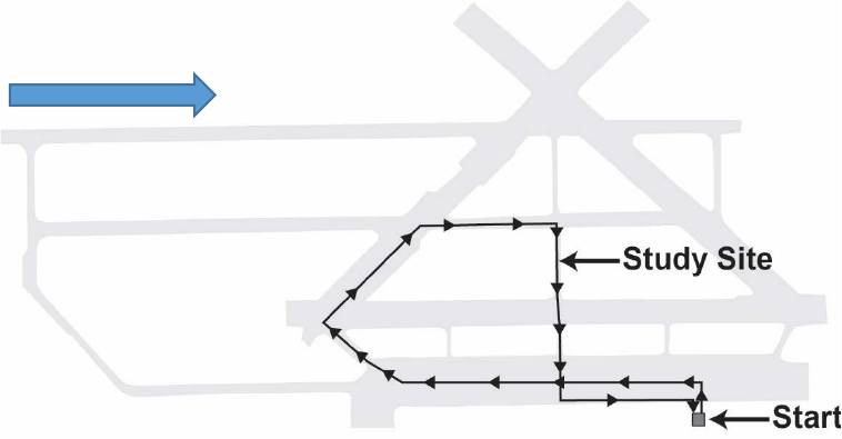
14
The location of the LEDs used in this study included the following:
• LEDs in rectangular beacons located above the sign. The bottom edge of the beacon
housing was approximately 11.6 ft from the pavement.
• LEDs in rectangular beacons located below the sign. The bottom edge of the beacon
housing was approximately 7.0 ft from the pavement.
• LEDs embedded within the sign. The height to the middle of the sign was approximately
9.5 ft.
Study Site
At the beginning of each participant run, the participants drove a Texas A&M Transportation
Institute (TTI) vehicle to the study site (see figure 2) and parked the vehicle near the orange
barrel (see figure 3 and figure 4). Figure 4 shows a photograph of the view for the participants.
At the site, the participants saw two study assemblies: one on each side of the two-lane street.
Vehicles were parked on the cross street upstream and downstream of the study site to aid in
giving the urban feel and to provide a hiding space for the technicians that were changing the
LED settings and moving the pedestrian cutout. Transverse white pavement crosswalk markings
were installed at the site (see figure 5).
Figure 2. Illustration. Route for closed-course study.
N
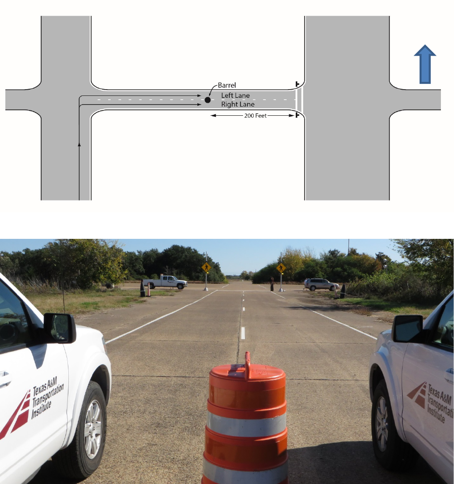
15
Figure 3. Illustration. Layout for the study site.
Figure 4. Photo. View of the study assemblies.
N
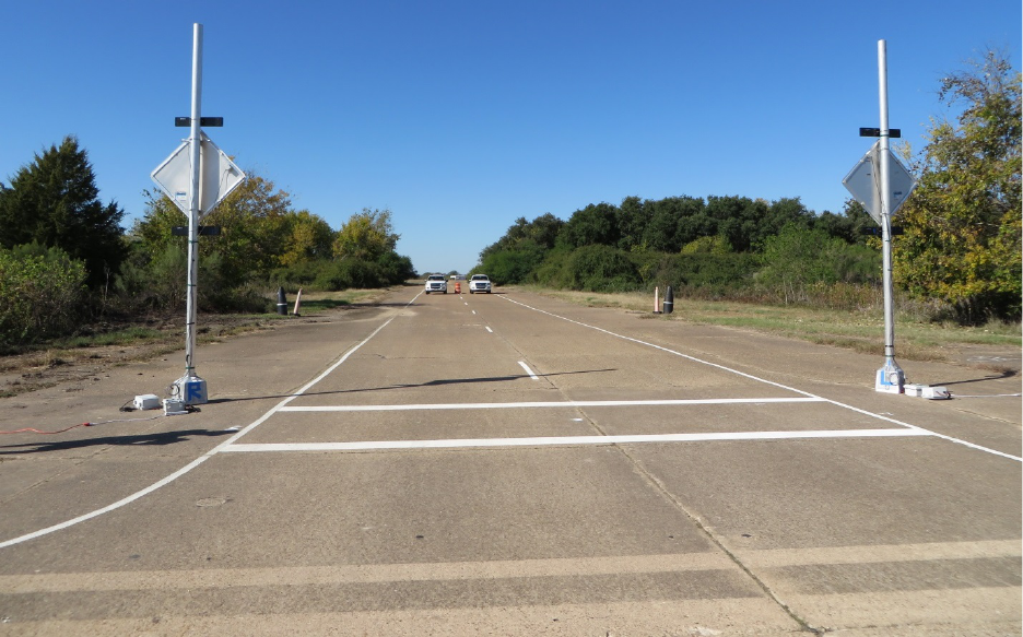
16
Figure 5. Photo. Back view of study site.
To be more efficient, the study was designed so that data were collected from two participants
simultaneously. Each participant was in a unique car so that a participant’s response would not
be heard by the other participant. The vehicles were parked next to each other at the study site,
thus simulating vehicles approaching a pedestrian crossing on a multilane roadway (see figure 3
and figure 4, which illustrate how the vehicles were parked). The participants were located 200 ft
from the LED assemblies. The 200-ft distance was selected because it represents stopping sight
distance (SSD) when traveling 30 mi/h.
(38)
Street lighting was present at the site for the nighttime testing. Two work zone light towers were
rented for the study and placed on either side of the approach on the cross street. During course
preparation, researchers positioned these light towers in a manner that simulated street lighting.
Prior to collecting data for each set of nighttime participants, the luminance reading at the
three pedestrian positions were taken to ensure a consistent street lighting level was present.
The average of these readings was about 26 lux.
Cutout Pedestrian
To ensure consistency with the pedestrian characteristics, the research team decided to use a
photograph of a pedestrian. The photograph was cut out to mimic the shape of a walking
pedestrian (see figure 6). Two cutouts were created to reflect two heights: adult and child. The
70-inch version reflected the average height of adults between 1999 and 2002, while the 54-inch
version reflected the average height of a child in the same time period.
(39)
Figure 7 shows a
researcher removing the short cutout photograph (center of road) after installing the tall cutout
photograph (right side of road).
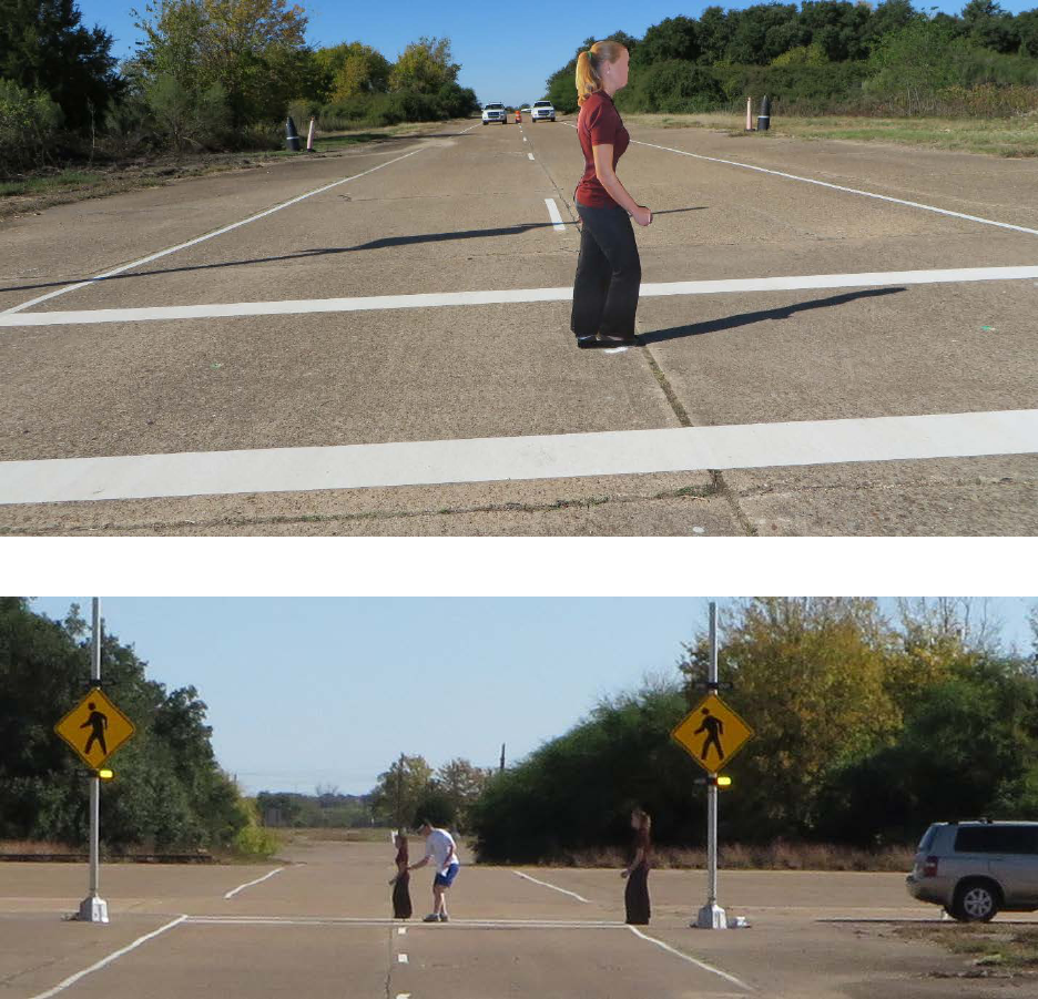
17
Figure 6. Photo. View of 54-inch cutout pedestrian used in study.
Figure 7. Photo. Researcher removing short cutout pedestrian after placing tall cutout
pedestrian.
The cutout photographs were glued on both sides of a pole that extended a few inches below
the shoe in the photograph. This extension was placed into one of three holes drilled into the
pavement. The holes were located just to the right of the edgeline in the center of the road (i.e.,
on the lane line) and just to the left of the edgeline, as shown in figure 8. The positions near the
edgeline pavement markings reflected the condition of a pedestrian waiting to cross the street.
The center of the street represented a pedestrian in the crosswalk. The holes were drilled between
the two crosswalk lines, as shown in figure 6 and figure 8. Because the photographs were glued
to both sides of the pole, the cutout pedestrian could be rotated to appear to be walking to the left
or to the right.
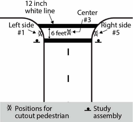
18
Figure 8. Illustration. Plan view showing pedestrian cutout positions.
Flash Pattern for Assemblies
Several flash patterns were used within the study. For the LEDs in rectangular beacons, the
patterns shown in table 3 were used. The light bar containing the rectangular beacons had
two unique beacons (with each beacon containing eight LEDs). When the beacon was turned on
varied depending on the beacon location (i.e., left side or right side), as illustrated in table 3.

19
Table 3. Flash patterns used with LEDs located in rectangular beacons
above or below the sign.
Cumulative
Time (ms)
Sets I and II:
No Flashes Dark
Set I: Wig-Wag
Alternating
Sets I and II:
2-5 Flash Pattern
Set II: Two 125-ms
Simultaneous
Pulses
Left
Time
On (ms)
Right
Time
On (ms)
Left
Time
On (ms)
Right
Time
On (ms)
Left
Time
On (ms)
Right
Time
On (ms)
Left
Time
On (ms)
Right
Time
On (ms)
0
0
0
25
0
25
0
25
25
25
0
0
25
0
25
0
25
25
50
0
0
25
0
25
0
25
25
75
0
0
25
0
25
0
25
25
100
0
0
25
0
25
0
25
25
125
0
0
25
0
0
0
0
0
150
0
0
25
0
0
0
0
0
175
0
0
25
0
0
0
0
0
200
0
0
25
0
25
0
25
25
225
0
0
25
0
25
0
25
25
250
0
0
25
0
25
0
25
25
275
0
0
25
0
25
0
25
25
300
0
0
25
0
25
0
25
25
325
0
0
25
0
0
0
0
0
350
0
0
25
0
0
0
0
0
375
0
0
25
0
0
0
0
0
400
0
0
25
0
0
25
0
0
425
0
0
25
0
0
0
0
0
450
0
0
25
0
0
25
0
0
475
0
0
25
0
0
0
0
0
500
0
0
0
25
0
25
0
0
525
0
0
0
25
0
0
0
0
550
0
0
0
25
0
25
0
0
575
0
0
0
25
0
0
0
0
600
0
0
0
25
0
25
0
0
625
0
0
0
25
0
25
0
0
650
0
0
0
25
0
25
0
0
675
0
0
0
25
0
25
0
0
700
0
0
0
25
0
25
0
0
725
0
0
0
25
0
25
0
0
750
0
0
0
25
0
25
0
0
775
0
0
0
25
0
25
0
0
800
0
0
0
25
BEC
BEC
BEC
BEC
825
0
0
0
25
BEC
BEC
BEC
BEC
850
0
0
0
25
BEC
BEC
BEC
BEC
875
0
0
0
25
BEC
BEC
BEC
BEC
900
0
0
0
25
BEC
BEC
BEC
BEC

20
925
0
0
0
25
BEC
BEC
BEC
BEC
950
0
0
0
25
BEC
BEC
BEC
BEC
975
0
0
0
25
BEC
BEC
BEC
BEC
Cycle length
(ms)
N/A
1,000
800
800
Number of
cycles/min
N/A
60
75
75
BEC = Beyond end of cycle.
N/A = Not applicable.
Note: Yellow shading represents when the beacons were on.
Table 4 shows the flash pattern used for the LEDs within the sign. While there are eight unique
points of lights within an embedded diamond sign, the researchers decided that all eight LEDs
would be illuminated at the same time within the sign as is currently used in practice. Therefore,
there was not a left and right designation for the LEDs within the sign. The 2-5 flash pattern used
with the assemblies was selected based on FHWA official interpretation 4(09)-21 (I) released
on June 13, 2012, regarding the RRFB.
(9)
It has two slower flashes on one side followed by
five rapid flashes on other side.
Table 4. Flash patterns used with LEDs within sign.
Cumulative
Time (ms)
Sets I and II:
No Flashing
Set I: Five Pulses
Similar to Right
Side of RRFB
Sets I and II:
One 100-ms Pulse
Set II: Two 125-ms
Pulses Similar to
Left Side of RRFB
Time On (ms)
Time On (ms)
Time On (ms)
Time On (ms)
0
0
0
25
25
25
0
0
25
25
50
0
0
25
25
75
0
0
25
25
100
0
0
0
25
125
0
0
0
0
150
0
0
0
0
175
0
0
0
0
200
0
0
0
25
225
0
0
0
25
250
0
0
0
25
275
0
0
0
25
300
0
0
0
25
325
0
0
0
0
350
0
0
0
0
375
0
0
0
0
400
0
25
0
0
425
0
0
0
0
450
0
25
0
0
475
0
0
0
0
500
0
25
0
0
525
0
0
0
0

21
550
0
25
0
0
575
0
0
0
0
600
0
25
0
0
625
0
25
0
0
650
0
25
0
0
675
0
25
0
0
700
0
25
0
0
725
0
25
0
0
750
0
25
0
0
775
0
25
0
0
800
0
BEC
0
BEC
825
0
BEC
0
BEC
850
0
BEC
0
BEC
875
0
BEC
0
BEC
900
0
BEC
0
BEC
925
0
BEC
0
BEC
950
0
BEC
0
BEC
975
0
BEC
0
BEC
Cycle length
(ms)
N/A
800
1,000
800
Number of
cycles/min
N/A
75
60
75
N/A = Not applicable.
Note: Yellow shading represents when the beacons were on.
Brightness of LEDs
The characteristics of the LEDs may affect the detection of pedestrians. Table 5 lists the
characteristics of the LEDs used with pattern set I, while table 6 provides similar values for
pattern set II. To quantify the brightness of the pulsing lights, researchers used the photometric
range within the TTI Visibility Laboratory. For each RRFB beacon and LED sign, a technician
measured the 95th percentile peak intensity (called “measured intensity” in table 5 and table 6)
and the optical power of the device. The researcher took the measurements at a vertical angle of
0 degrees and a horizontal angle of 0 degrees.
Peak luminous intensity is defined as the maximum luminous intensity for a given flash. The
peak intensity can be much higher than the typical intensity within a pulse. Therefore, the
95th percentile intensity is used to provide a more representative value. The 95th percentile
luminous intensity is the luminous intensity that 95 percent of the instantaneous intensity
measurements are less than or equal to during the duration of the flash; instantaneous intensities
measured during the dark period are not included in this measurement.
According to SAE Standard J595, optical power is defined as the integrated total of all flashes in
a minute, in candela-s/min.
(15)
Stated in a general way, optical power represents the area under
the curve. It provides an appreciation of both the intensity of the pulses and the amount of time
the LEDs are illuminated.

22
Table 5. LED characteristics for set I.
LED
Location
Flash Pattern
Target
Intensity
(Candela)
Measured
Intensity
(Candela)
Optical Power
(Candela-s/min)
Pulse Rate
(Number of
Pulses/Cycle
Length)
On Ratio
(Percent)
Above
2-5
600
622
25,600
8.75
69
Above
2-5
1,400
1,426
58,800
8.75
69
Above
2-5
2,200
2,207
91,000
8.75
69
Above
Wig-wag
600
605
36,300
2.00
100
Above
Wig-wag
1,400
1,442
86,500
2.00
100
Above
Wig-wag
2,200
2,237
134,200
2.00
100
Below
2-5
600
675
27,900
8.75
69
Below
2-5
1,400
1,450
59,800
8.75
69
Below
2-5
2,200
2,249
92,700
8.75
69
Below
Wig-wag
600
633
38,000
2.00
100
Below
Wig-wag
1,400
1,458
87,400
2.00
100
Below
Wig-wag
2,200
2,256
135,300
2.00
100
Within
100
600
649
3,900
1.00
10
Within
100
1,400
1,471
8,800
1.00
10
Within
100
2,200
2,225
13,300
1.00
10
Within
Five pulses
600
652
14,700
6.25
38
Within
Five pulses
1,400
1,454
32,700
6.25
38
Within
Five pulses
2,200
2,216
49,900
6.25
38
Note: Flash patterns are defined as follows: 2-5 = 2-5 flash pattern; wig-wag = wig-wag flash pattern; and 100 = one 100-ms
flash pattern.

23
Table 6. LED characteristics for set II.
LED
Location
Flash
Pattern
Target
Intensity
(Candela)
Measured
Intensity
(Candela)
Optical Power
(Candela-s/min)
Pulse Rate
(Number of
Pulses/Cycle
Length)
On Ratio
(Percent)
Above
125(2)
600
622
11,700
2.50
31
Above
125(2)
1,400
1,441
27,000
2.50
31
Above
125(2)
2,200
2,308
43,300
2.50
31
Above
2-5
600
622
25,600
8.75
69
Above
2-5
1,400
1,426
58,800
8.75
69
Above
2-5
2,200
2,207
91,000
8.75
69
Below
125(2)
600
619
11,600
2.50
31
Below
125(2)
1,400
1,436
26,900
2.50
31
Below
125(2)
2,200
2,269
42,500
2.50
31
Below
2-5
600
675
27,900
8.75
69
Below
2-5
1,400
1,450
59,800
8.75
69
Below
2-5
2,200
2,249
92,700
8.75
69
Within
100
600
652
3,900
1.00
10
Within
100
1,400
1,469
8,800
1.00
10
Within
100
2,200
2,227
13,400
1.00
10
Within
125(2)
600
646
12,100
2.50
31
Within
125(2)
1,400
1,464
27,400
2.50
31
Within
125(2)
2,200
2,227
41,800
2.50
31
Note: Flash patterns are defined as follows: 2-5 = 2-5 flash pattern; wig-wag = wig-wag flash pattern; 100 =
one 100-ms flash pattern; and 125(2) = two 125-ms flashes.
Previous research has demonstrated that LED characteristics can influence whether an object is
detected.
(40)
Because the amount of time the LEDs are on may influence a driver’s ability to
detect a pedestrian, a measure of the on time was developed. The on ratio variable (see table 5
and table 6) is defined to be the percentage of the 25-ms increments within a cycle where the
LEDs within the beacon or sign are illuminated. The percentage of the cycle where the LEDs are
dark would be determined as 1 minus the on ratio. For example, the 2-5 pattern would have an
off ratio of 31 percent (100 percent – 69 percent). In the wig-wag pattern, there was no dark
period, as demonstrated by having an on ratio of 100 percent. To provide an appreciation of how
often the LEDs are pulsing, the pulse rate was determined as the number of pulses divided by the
cycle length. For example, the 2-5 pattern had 7 pulses within the 0.8-s cycle for a pulse rate of
8.75, while the rapid-flashing LEDs within a sign had 5 pulses within the 0.8-s cycle for a pulse
rate of 6.25.
Combinations Studied
The variables for participant characteristics and site characteristics presented within this closed-
course study are as follows:
• Lighting: Day (natural lighting) or night (street lighting).
• Gender: Male or female.
24
• Age: Young (less than 55 years old) or old (55 years old or greater).
• Lane: Left lane or right lane.
• Viewing position: 200 ft upstream from assemblies.
Study assemblies characteristics included the following:
• LED location: LEDs in a rectangular beacon below the sign, LEDs in a rectangular
beacon above the sign, or LEDs within the sign.
• Flash pattern (three per set; see table 3 and table 4):
o Set I: No rectangular beacon above or below the sign, 2-5 pattern, or wig-wag
(alternating) pattern.
o Set I: No LEDs within the sign, five pulses (five pulses similar to the right side of the
RRFB), or one 100-ms pulse (single pulse).
o Set II: No rectangular beacon above or below the sign, 2-5 pattern, or two 125-ms
pulses (simultaneous).
o Set II: No LEDs within sign, five pulses (rapid right side of RRFB), or two 125-ms
pulses (two pulses similar to left side of RRFB).
• Target intensity (i.e., brightness): 0, 600, 1,400, and 2,200 candelas.
The cutout pedestrian characteristics include the following:
• Pedestrian position: None, right side, center, or left side.
• Pedestrian height (when present): Tall (70 inches) or short (54 inches).
• Pedestrian direction (when present): Left or right.
Over 260 tests would be needed for a participant to see all possible combinations of study
assembly and pedestrian characteristics. Preliminary data collection efforts demonstrated that
about 100 tests could be conducted within the available 60-min data collection period.
A presentation order of the possible combinations between the study assembly and cutout
pedestrian characteristics was developed using a random number generator in a spreadsheet.
The order was then modified so that a participant would only see a particular combination once
and so that a similar number of viewings per combination would occur. Table 7 shows the
combinations tested. A total of 15 tests were conducted for each combination of pedestrian
height and position. For example, the short cutout pedestrian when located in the center of the
roadway was viewed in 15 tests. For the 7 combinations possible when considering pedestrian
position and height, the 15 tests per combination resulted in a total of 105 tests per participant.
For those tests when a cutout pedestrian was present (105 − 15 = 90 tests), half of the tests had

25
the cutout pedestrian moving toward the left, while the other half of the tests had the cutout
pedestrian moving toward the right.
Initially, the goal was to randomize the presentation order for all characteristics tested (i.e., LED
location, flash pattern, brightness level, and cutout pedestrian position, height, and direction).
Preliminary efforts demonstrated that the changes required of the technicians to switch from
one LED location to another would consume too much time. Therefore, the study was subdivided
into three blocks. Within the first block, all the tests associated with one of the LED locations
would be conducted (e.g., rectangular below). A short break would be provided to the participant
while the field crew switched the wires to operate the next LED location (e.g., LED within sign).
Another break would divide the second block from the third block. Each block included 35 tests.
The presentation of the device order was different for different sets of participants; some
participants saw the above block first, some saw the below block first, and others saw the
LED sign block first.
Table 7. Number of variable combinations tested during the closed-course study.
Location
of LED
Flash
Pattern
Target
Intensity
(Candela)
Number of Tests
No
Pedestrian
Cutout
Present
Short Pedestrian
Cutout Position
Tall Pedestrian
Cutout Position
Total
Left
Side
Center
Right
Side
Left
Side
Center
Right
Side
Within
None
0
1
1
1
1
1
5
Other
600
1
1
1
1
1
5
1,400
1
1
1
1
1
5
2,200
1
1
1
1
1
5
Rapid
600
1
1
1
1
1
5
1,400
1
1
1
1
1
5
2,200
1
1
1
1
1
5
Below
None
0
1
1
1
1
1
5
Other
600
1
1
1
1
1
5
1,400
1
1
1
1
1
5
2,200
1
1
1
1
1
5
Rapid
600
1
1
1
1
1
5
1,400
1
1
1
1
1
5
2,200
1
1
1
1
1
5
Above
None
0
1
1
1
1
1
5
Other
600
1
1
1
1
1
5
1,400
1
1
1
1
1
5
2,200
1
1
1
1
1
5
Rapid
600
1
1
1
1
1
5
1,400
1
1
1
1
1
5
2,200
1
1
1
1
1
5
Grand Total
15
15
15
15
15
15
15
105
Note: Blank cells indicate that the combination was not tested.
26
Note that within the table, flash patterns are defined as follows:
• None: LEDs were not illuminated.
• Rapid: The 2-5 pattern was used when LEDs were above or below the sign, while
five pulses (five pulses similar to the right side of the RRFB) were used when the LEDs
were located within the sign.
• Other:
o Set I: Wig-wag (alternating) was used when LEDs were above or below the sign, and
a 100-ms pulse (single pulse) was used when LEDs were within the sign.
o Set II: Two 125-ms pulses (simultaneous) were used when LEDs were above or
below the sign, while two 125-ms pulses (two pulses similar to left side of RRFB)
were used when LEDs were within the sign.
Concluding Survey
After participants completed the closed-course portion of the study, they were asked to complete
a laptop survey that asked a series of queries to obtain the participants’ opinions regarding flash
patterns for beacons used with pedestrian crossing signs. The two initial queries included a video
filmed from a driver’s position as the vehicle moved toward a crosswalk with a waiting
pedestrian. The participants always saw the same sign assembly; however, the LEDs and flash
pattern used (if any) varied between the two queries. The same question was used with each
query. Figure 9 shows the starting view for the first two queries (a close-up example of the sign
assembly is shown in figure 1). The wording of the question and answers used with queries 1 and
2 are as follows:
As a driver of an automobile approaching the crosswalk shown in the video, how would you
react in this situation?
1. I would slow and allow the pedestrian to cross the roadway.
2. I would stop and allow the pedestrian to cross the roadway.
3. I would confirm the pedestrian is not crossing before proceeding.
4. I would continue driving at the same speed.
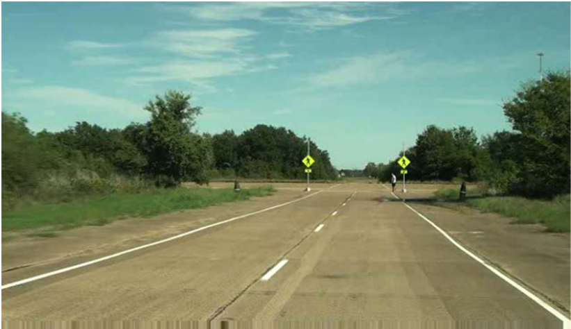
27
Figure 9. Photo. View at start of the driving video for the concluding survey for
queries 1 and 2.
Researchers wanted to determine how drivers viewed the requirement to yield to the pedestrian
when a pedestrian crossing sign did not have active supplemental LEDs. Therefore, the video for
one of the two initial queries for all participants had no LEDs active (condition termed “sign”
within the survey and is similar to the flash pattern “none” when wearing the occlusion glasses).
About half of the participants had the sign-only video with their first query, while the other half
of the participants had the sign-only video with their second query. Table 8 lists the videos
shown for each query by participant group.
Table 9 identifies the flash pattern used with queries 1 and 2, which were the moving videos
shown from a driver’s perspective. Table 10 shows illustrations of the flash patterns used
with queries 3 and 4, which were stationary videos showing a close-up of the pedestrian
crossing assembly.

28
Table 8. Video assignments and flash patterns for each query by participant group.
Participant
Group
Driving Video Flash Pattern
Stationary Video Flash Pattern
Query 1
Query 2
Query 3
Query 4
Video at Top of
Screen
Video at Top of
Screen
Video A at Left
Side of Screen
Video B at Right
Side of Screen
Video A at Left
Side of Screen
Video B at Right
Side of Screen
A
Sign
Below; 2-5
Within; 100
Below; 25(4)+200
Within; 125(2)
Below; 125(2)
B
Sign
Below; wig-wag
Below; 25(4)+200
Within; 25(4)+200
Sign
Within; 125(2)
C
Sign
Within; 100
Below; 25(4)+200
Within; 100
Below; 25(4)+200
Within; 125(2)
D
Below; 2-5
Sign
Below; 125(2)
Below; 2-5
Within; 25(4)+200
Within; 125(2)
E
Below; wig-wag
Sign
Within; 100
Within; 25(4)+200
Within; 100
Within; 125(2)
F
Within; 100
Sign
Within; 100
Below; 2-5
Sign
Within; 25(4)+200
G
Sign
Below; 2-5
Within; 125(2)
Within; 25(4)+200
Sign
Within; 100
H
Sign
Below; wig-wag
Sign
Below; 125(2)
Within; 25(4)+200
Sign
I
Sign
Within; 100
Below; 125(2)
Within; 25(4)+200
Below; 2-5
Sign
J
Below; 2-5
Sign
Within; 25(4)+200
Below; 125(2)
Below; 2-5
Within; 125(2)
K
Below; wig-wag
Sign
Below; 125(2)
Within; 100
Within; 25(4)+200
Below; 2-5
L
Within; 100
Sign
Within; 125(2)
Sign
Within; 125(2)
Within; 100
M
Sign
Below; 2-5
Below; 125(2)
Below; 25(4)+200
Below 25(4)+200
Below; 125(2)
N
Sign
Below; wig-wag
Below; 2-5
Within; 100
Within; 25(4)+200
Within; 100
O
Sign
Within; 100
Below; 2-5
Within; 25(4)+200
Within; 25(4)+200
Below; 25(4)+200
P
Below; 2-5
Sign
Below; 25(4)+200
Sign
Within; 100
Sign
Q
Below; wig-wag
Sign
Within; 125(2)
Below; 25(4)+200
Below; 2-5
Below; 25(4)+200
R
Within; 100
Sign
Sign
Below; 2-5
Within; 100
Below; 125(2)
S
Sign
Below; 2-5
Below; 125(2)
Sign
Within; 125(2)
Below; 2-5
T
Sign
Below; wig-wag
Sign
Below; 25(4)+200
Below; 25(4)+200
Below; 2-5
U
Sign
Within; 100
Below; 2-5
Below; 125(2)
Below; 125(2)
Within; 125(2)
Note: Flash patterns are defined as follows: sign = no active LEDs; 2-5 = 2-5 flash pattern; wig-wag = wig-wag flash pattern; 100 = one 100-ms flash pattern;
25(4)+200 = four 25-ms flashes and one 200-ms flash; and 125(2) = two 125-ms flashes.

29
Table 9. Flash patterns for queries 1 and 2 showing moving videos from driver perspective.
Cumulative
Time
(ms)
Below; Wig-Wag
Flash Pattern
Below; 2-5 Flash Pattern
Within; 100-ms
Flash Pattern
No LEDs or
Flash Pattern
Left Time
On (ms)
Right Time
On (ms)
Left Time
On (ms)
Right Time
On (ms)
Time On (ms)
Time On (ms)
0
25
0
25
0
25
0
25
25
0
25
0
25
0
50
25
0
25
0
25
0
75
25
0
25
0
25
0
100
25
0
25
0
0
0
125
25
0
0
0
0
0
150
25
0
0
0
0
0
175
25
0
0
0
0
0
200
25
0
25
0
0
0
225
25
0
25
0
0
0
250
25
0
25
0
0
0
275
25
0
25
0
0
0
300
25
0
25
0
0
0
325
25
0
0
0
0
0
350
25
0
0
0
0
0
375
25
0
0
0
0
0
400
25
0
0
25
0
0
425
25
0
0
0
0
0
450
25
0
0
25
0
0
475
25
0
0
0
0
0
500
0
25
0
25
0
0
525
0
25
0
0
0
0
550
0
25
0
25
0
0
575
0
25
0
0
0
0
600
0
25
0
25
0
0
625
0
25
0
25
0
0
650
0
25
0
25
0
0
675
0
25
0
25
0
0
700
0
25
0
25
0
0
725
0
25
0
25
0
0
750
0
25
0
25
0
0
775
0
25
0
25
0
0
800
0
25
BEC
BEC
BEC
0
825
0
25
BEC
BEC
BEC
0
850
0
25
BEC
BEC
BEC
0
875
0
25
BEC
BEC
BEC
0
900
0
25
BEC
BEC
BEC
0
925
0
25
BEC
BEC
BEC
0
950
0
25
BEC
BEC
BEC
0
975
0
25
BEC
BEC
BEC
0
Note: Yellow shading represents when the beacons were on.
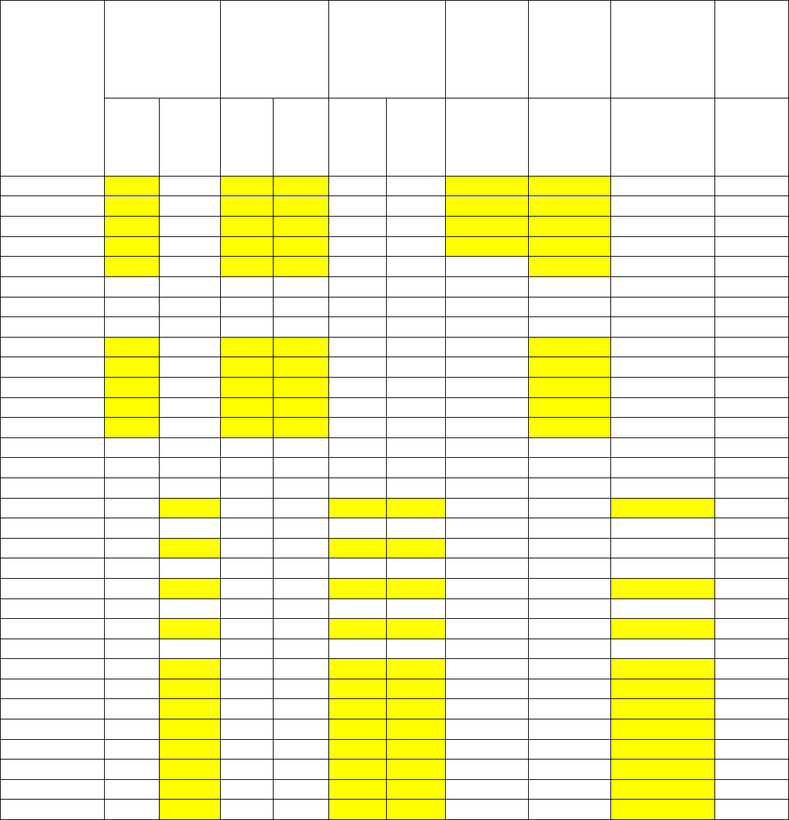
30
Table 10. Flash patterns used for queries 3 and 4 with the video showing a close-up view.
Cumulative
Time
(ms)
Below; 2-5
Flash Pattern
Below;
Two 125-ms
Flashes
Below;
Four 25-ms
Flashes and
One 200-ms
Flash
Within;
100-ms
Flash
Pattern
Within;
Two
125-ms
Flashes
Within;
Four 25-ms
Flashes and
One 200-ms
Flash
No
Flash
Pattern
Left
Time
On
(ms)
Right
Time
On
(ms)
Left
Time
On
(ms)
Right
Time
On
(ms)
Left
Time
On
(ms)
Right
Time
On
(ms)
Time On
(ms)
Time On
(ms)
Time On
(ms)
Time
On
(ms)
0
25
0
25
25
0
0
25
25
0
0
25
25
0
25
25
0
0
25
25
0
0
50
25
0
25
25
0
0
25
25
0
0
75
25
0
25
25
0
0
25
25
0
0
100
25
0
25
25
0
0
0
25
0
0
125
0
0
0
0
0
0
0
0
0
0
150
0
0
0
0
0
0
0
0
0
0
175
0
0
0
0
0
0
0
0
0
0
200
25
0
25
25
0
0
0
25
0
0
225
25
0
25
25
0
0
0
25
0
0
250
25
0
25
25
0
0
0
25
0
0
275
25
0
25
25
0
0
0
25
0
0
300
25
0
25
25
0
0
0
25
0
0
325
0
0
0
0
0
0
0
0
0
0
350
0
0
0
0
0
0
0
0
0
0
375
0
0
0
0
0
0
0
0
0
0
400
0
25
0
0
25
25
0
0
25
0
425
0
0
0
0
0
0
0
0
0
0
450
0
25
0
0
25
25
0
0
25
0
475
0
0
0
0
0
0
0
0
0
0
500
0
25
0
0
25
25
0
0
25
0
525
0
0
0
0
0
0
0
0
0
0
550
0
25
0
0
25
25
0
0
25
0
575
0
0
0
0
0
0
0
0
0
0
600
0
25
0
0
25
25
0
0
25
0
625
0
25
0
0
25
25
0
0
25
0
650
0
25
0
0
25
25
0
0
25
0
675
0
25
0
0
25
25
0
0
25
0
700
0
25
0
0
25
25
0
0
25
0
725
0
25
0
0
25
25
0
0
25
0
750
0
25
0
0
25
25
0
0
25
0
775
0
25
0
0
25
25
0
0
25
0
Note: Yellow shading represents when the beacons were on.
31
Queries 3 and 4 asked the participants to judge the urgency of the message conveyed by the
crosswalk treatment. The participants saw a close-up of two side-by-side assemblies labeled
video A and video B. The flash patterns and which LEDs were active varied, as listed in table 8.
The design of the study resulted in four to five participants seeing each pair with the specific
placement on the screen (i.e., left side or right side). If placement on the screen was not
considered, then each device pair was viewed, on average, by nine participants. The wording
of the question and answers used with queries 3 and 4 were as follows:
In your opinion, which video conveys a more urgent need for a driver to yield to a pedestrian?
1. Video A conveys a more urgent need.
2. Video B conveys a more urgent need.
3. The level of urgency is similar in both videos.
4. Neither video conveys an urgent need for a driver to yield to a pedestrian.
The final query asked the participants to count how many flashes they observed in the left and
right beacons for a light bar that was located in the room with them.
DATA COLLECTION
Study Periods
The study was conducted under both daytime and nighttime conditions between Wednesday,
November 13, 2013, and Thursday, December 12, 2013, with several days lost due to rain.
Sunset occurred at approximately 5:30 p.m. during the study. The study took about 1.5 h from
meeting the participant to the participant receiving their payment. About one-third of the
participants drove during daylight hours, and two-thirds drove during nighttime conditions
with an approximately even split between flash pattern sets I and II. The following start times
were used:
• 12 p.m.
• 1:30 p.m.
• 6:30 p.m.
• 8 p.m.
Participants
Participants were recruited from the area using TTI’s pool of previous research subjects list.
Over the phone, the potential participants were told that the study was confidential and the
records of the study would be kept private. They were also told that their participation was
voluntary and that they were free to withdraw from the study at any time.

32
The initial intent was to recruit a group of participants composed of one-quarter males over the
age of 55, one-quarter females over the age of 55, one-quarter males under the age of 55, and
one-quarter females under the age of 55. Within each of those demographic groups, the goal was
to have an even distribution between those who participated during the daytime and nighttime
within pattern set I. Therefore, the following divisions were used in structuring participant
recruitment:
• Light level: Day or night.
• Age group: Young (younger than 55 years old) and old (55 years old or older).
• Gender: Male or female.
When pattern set II was added to the study, data were only collected during the nighttime.
The male/female, young/old divisions resulted in four participant categories. The research goal
was to have 8 participants in each of these categories, resulting in 32 participants per day or per
night. Table 11 summarizes the number of participants by pattern set (I or II) and light level (day
or night) that participated in the study.
Participants were at least 18 years old and possessed a valid driver’s license with no restrictions.
Upon completion of the survey, participants received monetary compensation of $50.
Table 11. Distribution of participants.
Day or
Night
Pattern
Set
Old
Female
Old
Male
Old
Total
Young
Female
Young
Male
Young
Total
Young
Total
Day
I
9
8
17
8
7
15
32
Night
I
8
7
15
8
9
17
32
Night
II
8
8
16
9
9
18
34
Grand Total
25
23
48
25
25
50
98
Participant’s Tasks
The tasks for the participants for this closed-course study were as follows:
1. After vision was restored by the occlusion glasses, participants were asked to indicate via a
button push whether the pedestrian was walking to the left or to the right.
2. Following the driver’s identification of the pedestrian direction, participants were asked to
state whether the intensity of the LEDs was comfortable, irritating, or unbearable.
3. Participants responded to survey queries presented in a conference room at the conclusion of
the study.
Instrumented Vehicle
Two similar vehicles—2009 sports utility vehicles—served as the participant cars for this
experiment. The headlamps for these vehicles were 35 inches from the ground and 27 inches
33
from center of the vehicle. Prior to the start of the study, the headlamps on both vehicles were
properly aligned by TTI staff members.
Participant Intake
Participant intake was headquartered at TTI’s Environmental Emissions Research Facility on the
Riverside campus. This location was selected because it was near the driving route, had public
parking available, included restroom facilities, and was available for both daytime and nighttime
use during the data collection period. After meeting with a member of the research team to review
the informed consent documentation and complete the demographic questionnaire, participants
were given an overview of the study, including how the data were to be collected. They were also
given a Dvorine color vision test.
To ensure consistency, the research team used scripts and slide shows to aid in providing
instructions to each participant. The script used during intake was as follows:
“Now, let me tell you a little about your tasks. There are two parts. For the first part, you will be
driving a State-owned passenger vehicle on a closed course we have set up on airport runways,
taxiway, and roadways here at the Riverside campus. The vehicle is specially equipped to record
and measure various driving characteristics, but drives just like a normal car. A researcher will
be in the car with you at all times and will direct you when, where, and how fast you will need to
go. The fastest you will be asked to drive is 40 mi/h.
For one part, you will be driving a course marked with white and yellow striping just as you
would see on an actual road. Part of the route is not striped, and when we reach these segments,
I will point you to the reflective pavement markings/line in the pavement that will act as our
road’s “center line.” Once we arrive to the study location, we will ask you to park your vehicle
next to the orange barrels. There will be another participant in a vehicle next to you. We are
running two participants simultaneously to more efficiently collect data for this study.
Once the vehicle is in position we will ask you to place it into park. We will then ask you to place
the occlusion glasses over your eyes and glasses if you have glasses. The occlusion glasses will
block your vision until the start of the test. When you are ready, we will clear the occlusion
glasses and restore your vision. You are to tell us via a button push whether the pedestrian in the
downstream crosswalk is walking to the left, to the right, or is not present. We will practice the
button pushes prior to driving to the study sites. After you indicate which way the pedestrian is
walking, I will ask you to indicate if the beacon glare is comfortable, irritating, or unbearable.
• Comfortable (where the glare is not annoying and the signal is easy to look at).
• Irritating (where the glare is uncomfortable, however you are still able to look at it
without the urge to look away).
• Unbearable (where the glare is so intense that you want to avoid looking at it).
After completing the tests you will return here for a brief laptop survey. After the laptop survey
we will provide your payment.”
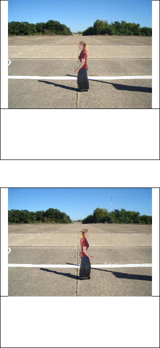
34
Initial Button Push Training
As part of the intake process, the participants practiced with a button box while responding to
photographs of the crossing. The objectives for this part of the study were as follows:
• Train participants to recognize the pedestrians as well as absence of the pedestrians.
• Provide the opportunity for the participants to become familiar with using three buttons
to record their responses.
During the training tests, the participant pressed a button when they determined the direction the
pedestrian was walking. Because of the software used for this test and available response pads
for this software, the button box used for this training had seven buttons. Figure 10 through
figure 12 show three of the photos along with the accompanying instructions used in the initial
training. A random mix of tall and short cutout pedestrians moving to the right and to the left and
in positions 1, 3, or 5 (illustrated in figure 8) were used within the training.
When the pedestrian in the
crosswalk is moving to the left
(as shown) please press (3)
(do so now).
Figure 10. Photo. Training example with pedestrian facing left.
When the pedestrian in the
crosswalk is moving to the right
(as shown) please press (5)
(do so now).
Figure 11. Photo. Training example with pedestrian facing right.
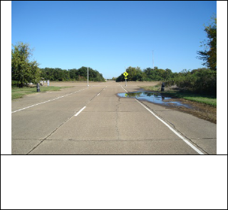
35
When no pedestrian is present in
the crosswalk (as shown) please
press (4) (do so now).
Figure 12. Photo. Training example with no pedestrian.
Vehicle Review
Participants were escorted to the TTI vehicle and given a walk-through of the vehicle’s features.
They were provided with the opportunity to adjust the seat and mirrors and to become
accustomed to the controls of the vehicle.
Participants were informed that they would drive the vehicle on a closed course and were told to
drive at a speed not exceeding 40 mi/h on the runways. They were asked to drive the runway
system as though it was a regular roadway and were reminded that they had complete control of
the vehicle at all times. A researcher accompanied the participant in the back seat, controlling the
data collection equipment and providing direction. Participants were told to keep the vehicle’s
headlamps on the low setting if testing at night. They were told to drive to the study site and to
position the vehicle by the barrel. Once in position, they were told to place the vehicle into park.
Data Collection at Study Site
At the study site, the participants were reminded that they would be wearing occlusion glasses
that would block their vision until the start of the test and that they would provide responses via
a three-button box within the vehicle. The researcher handed the participant the button box and
asked them to become acquainted with the button box and to determine how best to hold the box
comfortably in their hands. When the participant indicated they were comfortable with the box,
they were provided the occlusion glasses, which they placed on their face over their eyeglasses if
they were wearing any.
After the participants indicated that the glasses and button box were comfortable, the practice
testing began for at least three scenarios. After the practice, the testing began. When the
participant had indicated readiness and the field crew indicated readiness for the cutout
pedestrian and study assembly, the researcher cleared the glasses and restored vision. The
participants were then asked to indicate via a pushbutton whether the pedestrian in the
downstream crosswalk was walking to the left or to the right or whether the pedestrian was
not present.
36
The participants were provided the following instruction in case they felt the brightness was too
bright for them:
If you find the brightness level of the beacons to be agonizing and you are not comfortable
completing the task for a particular test, please look away from the crosswalk and tell me. I will
block your vision for that test and will radio the field crew to setup for the next test.
After the participants pushed a button on the button box, which would darken the glasses, they
were to provide their rating of the brightness of the lights on the traffic control device. The
three rating levels used were as follows:
• Comfortable: The glare was not annoying, and the signal was easy to look at.
• Irritating: The glare was uncomfortable; however, participants could still look at it
without the urge to look away.
• Unbearable: The glare was so intense that participants wanted to avoid looking at it.
After the participants indicated the rating level, the researcher radioed the field crew and told
them to set up for the next test. This process was repeated until the participants had completed all
the tests at the site.
The participants were also provided these additional instructions:
If at any point in time you wish to stop, or would like a break, let me know and we will stop
or allow you an opportunity to rest.
Please leave the vehicle in park during these tests and while you are wearing the
occlusion glasses.
DATA REDUCTION
Participant Demographics
Table 12 lists the demographic information for the 98 participants. The large number that
selected retired for employment (34 percent) is a reflection of the emphasis on having half of the
drivers over 55 years old.

37
Table 12. Demographic information for participants.
Characteristic
Set I, Day
Set I, Night
Set II, Night
Total
Number
Percent
Number
Percent
Number
Percent
Number
Percent
Gender
Female
17
53
16
50
17
50
50
51
Male
15
47
16
50
17
50
48
49
Age group
< 55 years old
17
53
15
47
16
47
48
49
≥ 55 years old
15
47
17
53
18
53
50
51
Employment
Full time
11
34
12
37
13
38
36
37
Part time
4
13
2
6
4
12
10
10
Retired
13
41
10
31
10
29
33
34
Student/part
time
1
3
4
13
5
15
10
10
Other
3
9
4
13
2
6
9
9
Miles driven
per year
< 10,000 mi
5
16
5
16
6
18
16
16
10,000–
15,000 mi
14
44
14
44
15
44
43
44
> 15,000 mi
13
41
13
41
13
38
39
40
Normal
driving
conditions
Rural roads
9
28
7
22
11
32
27
28
City streets
15
47
16
50
12
35
43
44
Freeways
1
3
3
9
0
0
4
4
Mixed
7
22
6
19
11
32
24
24
Data Cleaning
Before proceeding with the statistical analyses, the data were reviewed to identify and remove
tests that needed to be eliminated due to miscoded information regarding the response type, the
wrong LEDs being activated in the assembly, or incorrect pedestrian size, position, or direction.
In a few cases, participants would self-correct a button push. To have all response times only
reflect initial reactions, the detection time results for a given test with duplicate responses were
eliminated. These data were included in the detection accuracy evaluations. Instances where
animals crossed in front of the vehicles were eliminated as well.
Responses
The computer software program along with the response pad unit were used to record the time
between the occlusion glasses being cleared and the participants pressing a button in the response
pad. These data were recorded within a spreadsheet that contained an experiment label, a time
stamp, and the corresponding detection time. For each experiment, the researcher asked about the
glare immediately after each participant pressed a button in the response pad. The experimenters
manually recorded discomfort glare ratings using preprinted data sheets.
Each of the experiment labels corresponded to predetermined combinations of pedestrian height,
position, brightness, and flash pattern. The sequence of experiments was random within the
blocking structure described previously in this report. The spreadsheet with detection time data
was later combined with the corresponding experiment conditions and discomfort data per
experiment label.
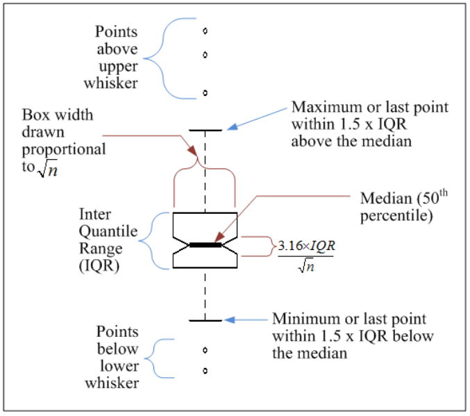
38
Box Plots
For some analyses, results were presented visually in the form of box plots or quantitatively in
the form of statistical analysis. Box plots presented in this report were generated using the
convention that the central line in the box represents the median data point (see figure 13). The
top of the box represents the 75th percentile, and the bottom represents the 25th percentile. Thus,
the relative position of the median score within the 75th and 25th percentiles can give some
indication about the skewness of the data. The height of the box is known as the “interquartile
range” (IQR). The “whiskers” represent the data that lie 1.5 times beyond the IQR. If all data
below the 25th percentile and above the 75th percentile are within 1.5 times the IQR, then the
end of the whisker represents the greatest or smallest value. Otherwise, all outliers beyond
1.5 times the IQR, added or subtracted from the 25th and 75th percentiles, respectively, are
plotted using small black open circles.
Figure 13. Illustration. Box plot details.
Additionally, it should be noted that a box plot representing a large sample provides more
confidence on its quartiles than another box plot representing a smaller sample. For this reason,
when two or more box plots are drawn together, the following two metrics of sample sizes
are represented:
• The box plot width is drawn proportional to the square root of the sample size, n.
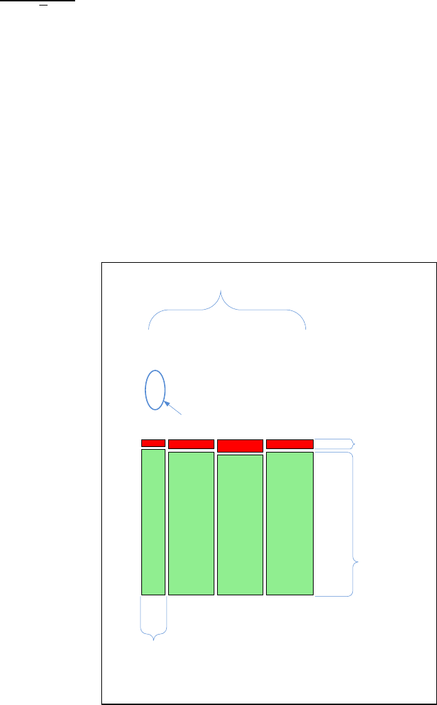
39
• A triangular notch is symmetrically cut around the median and has a total width of
. This feature allows a preliminary graphic assessment of differences of
medians, since such notch width has been proposed to roughly represent a 95 percent
confidence interval around the median.
(41)
For example, two medians are significantly
different if the notches of two box plots do not overlap, but nothing can be said (that is,
preliminarily) if there is overlap between notches.
Mosaic Plots
For some analyses, results were presented visually in the form of mosaic plots. Mosaic plots
divide each dimension of a rectangular space in sizes relative of the levels of a variable assigned
to that dimension. Thus, this type of plot can represent two variables at the time, where each
variable may have two or more levels. Figure 14 shows the details of a mosaic plot when the
variable assigned to the height is the number of correct/incorrect pedestrian detections.
Figure 14. Illustration. Mosaic plot details.
Potential Outliers
Preliminary statistical analyses were examined for outlying data points in the fit. Data points
identified in this way were tested for their impact on the analysis. Most of the cases identified in
this stage came from a young participant with distinctive fast detection times and high accuracy
3.16 × IQR
n
Variable X
Outcome
95
93
9
93
IncorrectCorrect
Levels of
variable X
Width drawn in
proportion to total
number of detections
in this level, relative to
all levels of X
Height drawn
proportional to
number of
incorrect
detections,
relative to all
detections in this
level of X
Height drawn
proportional to
number of correct
detections,
relative to all
detections in this
level of X
Proportion of correct
detections at this level
of X
40
in the daytime dataset. The data from this participant were identified in the analysis stage. The
analysis was tested for sensitivity to this subset, but it was verified that the conclusions remained
virtually unchanged, with or without these data. For robustness, results in this report include the
data from this participant.
FINDINGS
Detection Time to Correctly Identify Pedestrian Walking Direction
During the daytime, the average detection time to pedestrian direction was 1,137 ms from a
sample of 2,998 correct detections. At night, the average detection time was notably longer—
1,376 ms from a sample of 6,091 correct detections. This roughly represents a 25 percent
increase in detection time at night. Table 13 shows the average detection time for the daytime
data, while table 14 provides the nighttime average detection time for pattern set I. Nighttime
average detection time for pattern set II is in table 15 along with nighttime average for both
pattern sets I and II.

41
Table 13. Daytime average detection time for set I.
Target
Intensity
(Candela)
Flash
Pattern
Location
of LED
Older Participants
Younger Participants
Combined Participants
Number of
Participants
Average
Detection
Time
(ms)
Number of
Participants
Average
Detection
Time
(ms)
Number of
Participants
Average
Detection
Time
(ms)
600
100
Within
70
1,356
66
967
136
1,167
600
Five pulses
Within
73
1,170
65
1,015
138
1,097
600
2-5
Above
71
1,219
70
929
141
1,075
600
2-5
Below
82
1,336
63
1,068
145
1,220
600
Wig-wag
Above
74
1,197
70
907
144
1,056
600
Wig-wag
Below
81
1,200
63
963
144
1,096
1,400
100
Within
72
1,311
66
972
138
1,149
1,400
Five pulses
Within
73
1,211
67
968
140
1,095
1,400
2-5
Above
76
1,339
70
979
146
1,166
1,400
2-5
Below
82
1,276
62
969
144
1,144
1,400
Wig-wag
Above
75
1,318
70
960
145
1,145
1,400
Wig-wag
Below
79
1,247
65
938
144
1,107
2,200
100
Within
75
1,311
67
1,013
142
1,170
2,200
Five pulses
Within
74
1,286
68
972
142
1,136
2,200
2-5
Above
79
1,291
69
966
148
1,140
2,200
2-5
Below
81
1,566
62
1,065
143
1,349
2,200
Wig-wag
Above
77
1,333
70
912
147
1,132
2,200
Wig-wag
Below
81
1,332
62
1,025
143
1,199
None
Sign
Above
71
1,190
69
910
140
1,052
None
Sign
Below
83
1,240
65
985
148
1,128
None
Sign
Within
72
1,145
68
940
140
1,046
Total
1,601
1,281
1,397
971
2,998
1,137
Note: Flash patterns are defined as follows: 100 = one 100-ms flash pattern; 2-5 = 2-5 flash pattern; wig-wag = wig-wag flash pattern; and sign = no
active LEDs.

42
Table 14. Nighttime average detection time for set I.
Target
Intensity
(Candela)
Flash
Pattern
Location
of LED
Older Participants
Younger Participants
Combined Participants
Number of
Participants
Average
Detection
Time
(ms)
Number of
Participants
Average
Detection
Time
(ms)
Number of
Participants
Average
Detection
Time
(ms)
600
100
Within
70
1,781
81
1,106
151
1,419
600
Five pulses
Within
67
1,609
83
1,120
150
1,338
600
2-5
Above
69
1,525
83
1,208
152
1,352
600
2-5
Below
65
1,700
79
1,270
144
1,464
600
Wig-wag
Above
72
1,654
79
1,215
151
1,424
600
Wig-wag
Below
71
1,900
80
1,459
151
1,666
1,400
100
Within
69
1,609
80
1,184
149
1,380
1,400
Five pulses
Within
70
1,596
84
1,147
154
1,351
1,400
2-5
Above
68
1,511
81
1,237
149
1,362
1,400
2-5
Below
68
1,822
79
1,527
147
1,663
1,400
Wig-wag
Above
67
1,495
78
1,240
145
1,358
1,400
Wig-wag
Below
61
1,870
76
1,520
137
1,676
2,200
100
Within
70
1,526
85
1,098
155
1,291
2,200
Five pulses
Within
67
1,603
81
1,231
148
1,399
2,200
2-5
Above
67
1,623
82
1,298
149
1,444
2,200
2-5
Below
61
1,706
75
1,363
136
1,517
2,200
Wig-wag
Above
71
1,745
78
1,277
149
1,500
2,200
Wig-wag
Below
57
2,567
71
1,979
128
2,241
None
Sign
Above
68
1,345
83
1,173
151
1,250
None
Sign
Below
70
1,747
83
1,184
153
1,442
None
Sign
Within
70
1,500
84
1,059
154
1,260
Grand Total
1,418
1,680
1685
1,274
3,103
1,459
Note: Flash patterns are defined as follows: 100 = one 100-ms flash pattern; 2-5 = 2-5 flash pattern; wig-wag = wig-wag flash pattern; and sign = no
active LEDs.

43
Table 15. Nighttime average detection time for set II and combined total for sets I and II.
Target
Intensity
(Candela)
Flash
Pattern
Location
of LED
Older Participants
Younger Participants
Combined Participants
Number of
Participants
Average
Detection
Time
(ms)
Number of
Participants
Average
Detection
Time
(ms)
Number of
Participants
Average
Detection
Time
(ms)
600
100
Within
70
1,227
72
1,257
142
1,242
600
125(2)
Above
69
1,167
72
1,192
141
1,179
600
125(2)
Below
66
1,195
72
1,246
138
1,221
600
125(2)
Within
69
1,132
76
1,311
145
1,226
600
2-5
Above
71
1,254
77
1,262
148
1,258
600
2-5
Below
61
1,558
76
1,383
137
1,461
1,400
100
Within
67
1,218
75
1,350
142
1,287
1,400
125(2)
Above
69
1,170
76
1,322
145
1,250
1,400
125(2)
Below
73
1,236
73
1,302
146
1,269
1,400
125(2)
Within
69
1,191
72
1,327
141
1,260
1,400
2-5
Above
68
1,249
78
1,303
146
1,278
1,400
2-5
Below
63
1,479
74
1,451
137
1,464
2,200
100
Within
71
1,202
74
1,242
145
1,222
2,200
125(2)
Above
72
1,191
79
1,312
151
1,255
2,200
125(2)
Below
68
1,394
71
1,343
139
1,368
2,200
125(2)
Within
67
1,320
74
1,470
141
1,399
2,200
2-5
Above
66
1,304
78
1,412
144
1,362
2,200
2-5
Below
50
1,390
75
1,481
125
1,445
None
Sign
Above
67
1,224
80
1,158
147
1,188
None
Sign
Below
67
1,385
76
1,214
143
1,294
None
Sign
Within
72
1,189
73
1,217
145
1,203
Total Set II
1,415
1,265
1573
1,312
2,988
1,290
Combined Total Sets I and II
2,833
1,473
3258
1,292
6,091
1,376
Note: Flash patterns are defined as follows: 100 = one 100-ms flash pattern; 125(2) = two 125-ms flashes; 2-5 = 2-5 flash pattern; and sign = no
active LEDs.
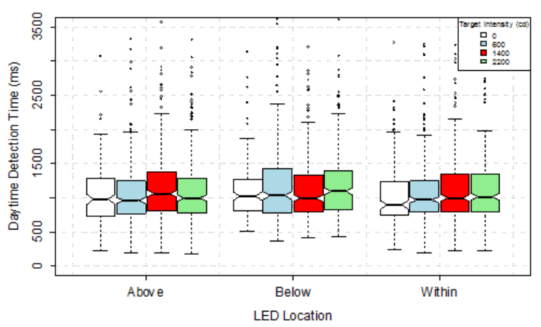
44
Box plots were generated to demonstrate trends in the data before conducting the formal
statistical analysis. The plots in figure 15 for daytime and figure 16 for nighttime demonstrate
that detection time tended to be shorter for lower intensity and longer for higher intensity
regardless of the location of the LEDs. This trend was more obvious at night (see figure 16).
The trends held even when the data were sorted by pedestrian position rather than LED locations
(see figure 17 for daytime and figure 18 for nighttime). The groups of boxes clearly tend to be
higher to the right of the plot, which corresponds to higher intensities.
Figure 17 and figure 18 demonstrate a clear trend regarding the pedestrian position in the
crosswalk. The time to correctly identify that there was no pedestrian in the crosswalk appears
similar at different levels of LED intensity and at day and nighttime (i.e., the green boxes). The
median detection time for that case was about 1,200 ms (i.e., the added horizontal line in the
plots). In all other correct responses, it is clear that nighttime had longer times, but the relative
trends appear constant; a pedestrian at the center of the crosswalk triggered faster detections than
either pedestrian at the right or the left side of the crosswalk.
Figure 15. Graph. Daytime detection time by LED location and target intensity.
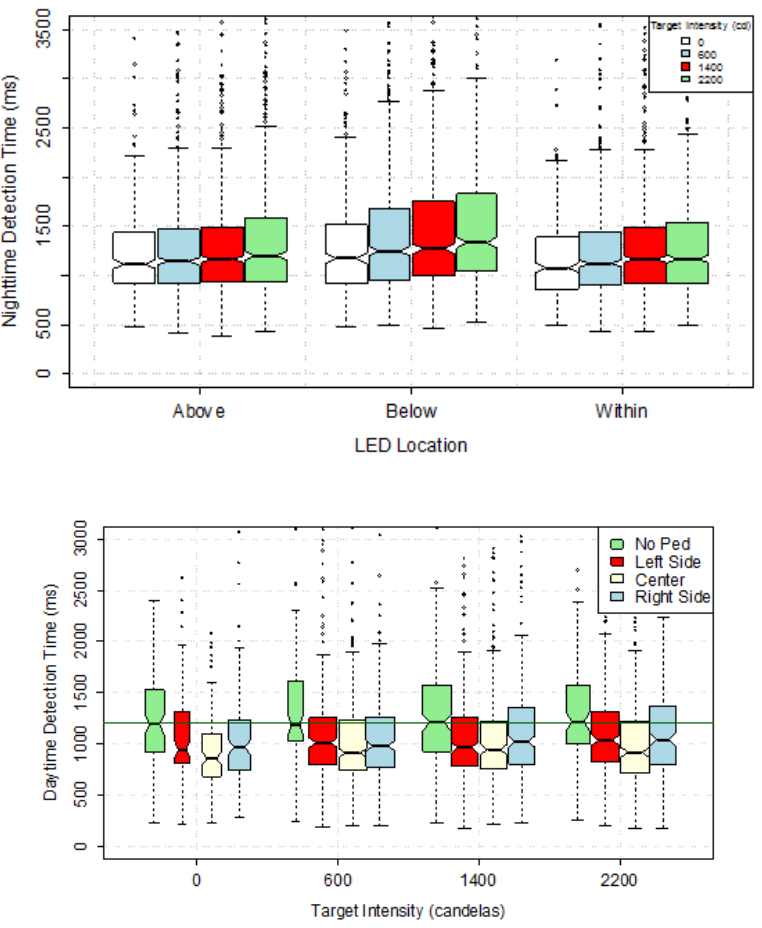
45
Figure 16. Graph. Nighttime detection time by LED location and target intensity.
Note: The horizontal line represents the median detection time.
Figure 17. Graph. Daytime detection time by pedestrian position and target intensity.
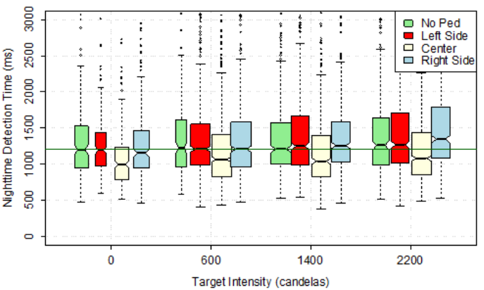
46
Note: The horizontal line represents the median detection time with no pedestrian present.
Figure 18. Graph. Nighttime detection time by pedestrian position and target intensity.
It should be noted that the plots make evident the fact that the data are heavily skewed toward
longer detection times, especially at night. This means that the data are more disperse at values
above the median than below the median. To control for this characteristic, the statistical analysis
was performed using the natural logarithm of the detection time. This data transformation
reduced the skewness while preserving the percentile ranks in the data. More details are provided
in the Statistical Analysis section in this chapter.
Accuracy of Detecting Pedestrian Direction
Accuracy of detecting pedestrian direction was determined by the number of participants who
correctly detected the direction of the cutout pedestrian to the number of participants for the
given characteristics (e.g., flash pattern, etc.). Table 16 shows the accuracy rate for daytime,
while table 17 shows similar data for nighttime. During the daytime, the average rate of correct
detections of pedestrian direction was 98 percent from a sample of 3,053 detections. At night, the
average detection rate was notably lower, 93 percent, from a sample of 6,515 detections.

47
Table 16. Daytime accuracy of correct detection for set I.
Target
Intensity
(Candela)
Flash
Pattern
Location
of LED
Older
Participant
Accuracy
(Percent)
Younger
Participant
Accuracy
(Percent)
All
Participant
Accuracy
(Percent)
Sample
Size
600
Five pulses
Within
99
98
99
140
600
Wig-wag
Above
93
100
96
150
600
Wig-wag
Below
95
98
97
149
600
100
Within
95
99
96
141
600
2-5
Above
97
100
99
143
600
2-5
Below
96
100
98
148
1,400
Five pulses
Within
99
100
99
141
1,400
Wig-wag
Above
96
100
98
148
1,400
Wig-wag
Below
98
100
99
146
1,400
100
Within
99
99
99
140
1,400
2-5
Above
97
100
99
148
1,400
2-5
Below
99
98
99
146
2,200
Five pulses
Within
100
100
100
142
2,200
Wig-wag
Above
100
100
100
147
2,200
Wig-wag
Below
95
97
96
149
2,200
100
Within
99
100
99
143
2,200
2-5
Above
99
99
99
150
2,200
2-5
Below
96
97
97
148
None
Sign
Above
96
100
98
143
None
Sign
Below
98
100
99
150
None
Sign
Within
99
100
99
141
Grand Total
97
99
98
3,053
Note: Flash patterns are defined as follows: wig-wag = wig-wag flash pattern; 100 = one 100-ms flash pattern;
2-5 = 2-5 flash pattern; and sign = no active LEDs.

48
Table 17. Nighttime accuracy of correct detection.
Target
Intensity
(Candela)
Flash
Pattern
Location
of LED
Set I
Set II
All
Participant
Accuracy
(Percent)
Sample
Size
Older
Participant
Accuracy
(Percent)
Younger
Participant
Accuracy
(Percent)
Older
Participant
Accuracy
(Percent)
Younger
Participant
Accuracy
(Percent)
600
Five pulses
Within
89
98
NS
NS
94
160
600
Wig-wag
Above
99
98
NS
NS
98
154
600
Wig-wag
Below
95
95
NS
NS
95
159
600
100
Within
93
98
93
91
94
312
600
125(2)
Above
NS
NS
92
92
92
153
600
125(2)
Below
NS
NS
90
92
91
151
600
125(2)
Within
NS
NS
92
96
94
154
600
2-5
Above
93
100
96
99
97
309
600
2-5
Below
87
95
84
95
90
311
1,400
Five pulses
Within
93
100
NS
NS
97
159
1,400
Wig-wag
Above
96
98
NS
NS
97
150
1,400
Wig-wag
Below
84
89
NS
NS
87
158
1,400
100
Within
92
98
92
96
94
308
1,400
125(2)
Above
NS
NS
92
96
94
154
1,400
125(2)
Below
NS
NS
99
94
96
152
1,400
125(2)
Within
NS
NS
92
96
94
150
1,400
2-5
Above
91
98
93
99
95
310
1,400
2-5
Below
91
94
85
93
91
313
2,200
Five pulses
Within
89
95
NS
NS
93
160
2,200
Wig-wag
Above
97
96
NS
NS
97
154
2,200
Wig-wag
Below
78
85
NS
NS
82
157
2,200
100
Within
93
100
95
95
96
313
2,200
125(2)
Above
NS
NS
96
99
97
155
2,200
125(2)
Below
NS
NS
92
92
92
151
2,200
125(2)
Within
NS
NS
89
95
92
153
2,200
2-5
Above
91
98
90
98
94
311

49
2,200
2-5
Below
82
89
71
94
85
308
None
Sign
Above
92
100
89
100
96
312
None
Sign
Below
95
100
92
95
95
310
None
Sign
Within
93
99
96
92
95
314
Grand Total
91
96
91
95
93
6,515
Note: Flash patterns are defined as follows: wig-wag = wig-wag flash pattern; 100 = one 100-ms flash pattern; 125(2) = two 125-ms flashes; 2-5 = 2-5 flash
pattern; and sign = no active LEDs.
NS = Flash pattern was not studied within the set.
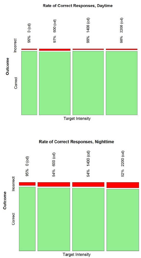
50
Mosaic plots were generated to demonstrate trends in the data before conducting a formal
statistical analysis. The plots in figure 19 and figure 20 demonstrate that the percent of
correct detections tends to be lower for higher target intensity at night. This trend is not seen
in the daytime data.
Figure 19. Graph. Daytime correct detection rate by target intensity.
Figure 20. Graph. Nighttime correct detection rate by target intensity.
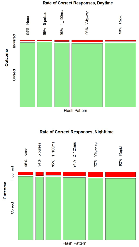
51
Figure 21 and figure 22 demonstrate that when subdividing the data by flash pattern, no trend
appeared clear for daytime. It appears that the 2-5 (rapid) and wig-wag patterns tended to have
slightly lower correct detection rates than the rest of patterns for nighttime condition.
Figure 21. Graph. Daytime correct detection rate by flash pattern.
Figure 22. Graph. Nighttime correct detection rate by flash pattern.
Finally, the trends by age are demonstrated by figure 23 for daytime and figure 24 for nighttime.
It seems clear the older participants tended to be less accurate than young participants.
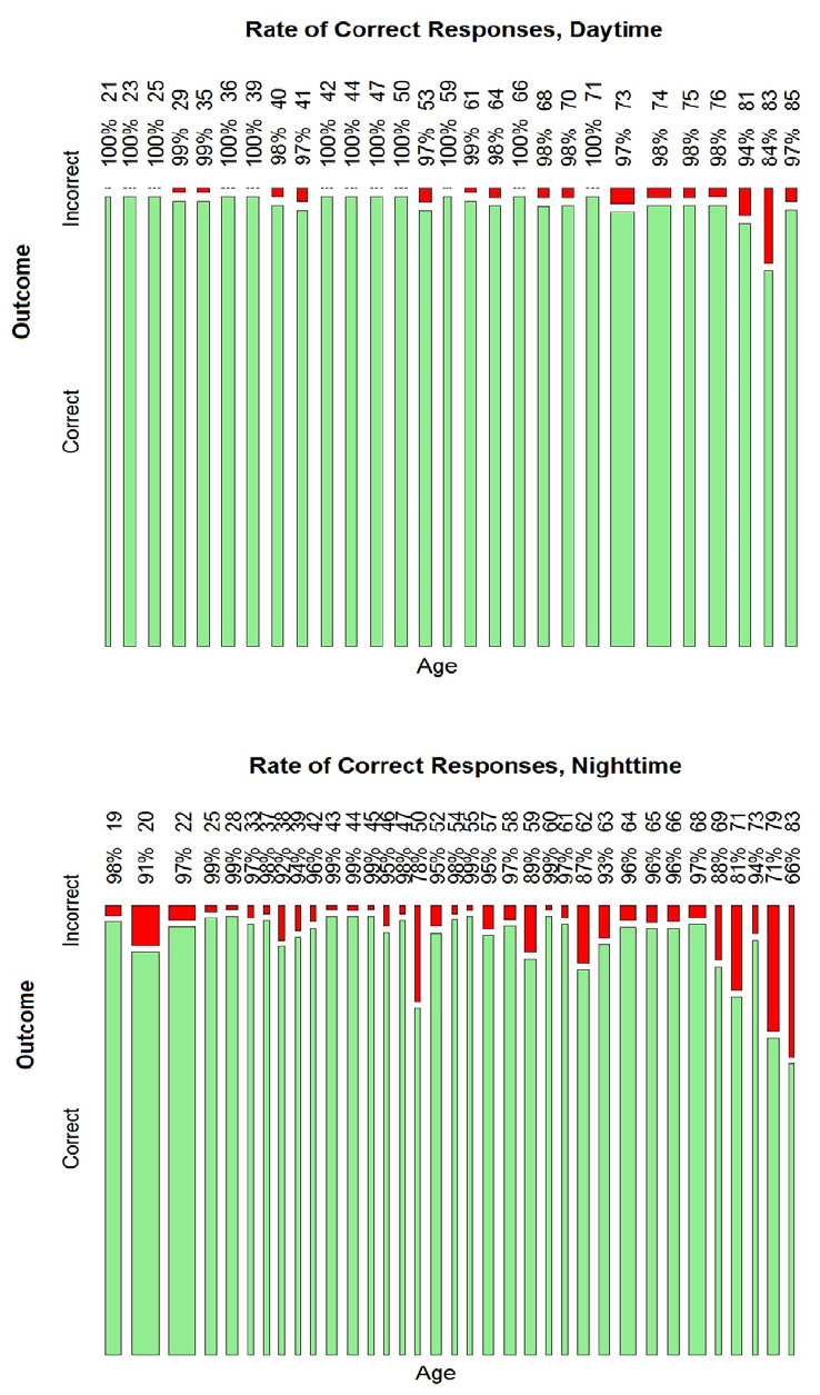
52
Figure 23. Graph. Daytime detection rate by age.
Figure 24. Graph. Nighttime detection rate by age.
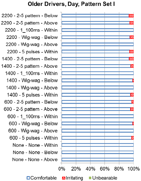
53
Discomfort
After the participants indicated the direction the cutout pedestrian was traveling, they stated
whether the intensity of the LEDs was comfortable, irritating, or unbearable. As expected,
during the daytime, almost all of the participants were comfortable with the LEDs, as shown
in figure 25 (older drivers) and figure 26 (younger drivers). Only the target intensity of
2,200 candelas was associated with more than a 10 percent level of irritating responses.
Figure 25. Graph. Older driver daytime discomfort rating for set I.
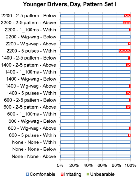
54
Figure 26. Graph. Younger driver daytime discomfort rating for set I.
During nighttime, more participants considered the LEDs to be unbearable, as illustrated
in figure 27 and figure 28 for set I and figure 29 and figure 30 for set II. Trends in the data
show that a larger proportion of the participants felt the flash patterns with the higher intensities
were irritating or unbearable. Within set I, the wig-wag pattern with a target intensity of
2,200 candelas had the lowest number of participants, indicating it was comfortable for both
older and younger drivers.
Reasons the participants gave an unbearable rating include the following:
• It was almost impossible to see the pedestrian.
• There was too much glare.
• Lights were too distracting.
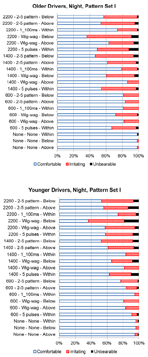
55
Figure 27. Graph. Older driver nighttime discomfort rating for set I.
Figure 28. Graph. Younger driver nighttime discomfort rating for set I.
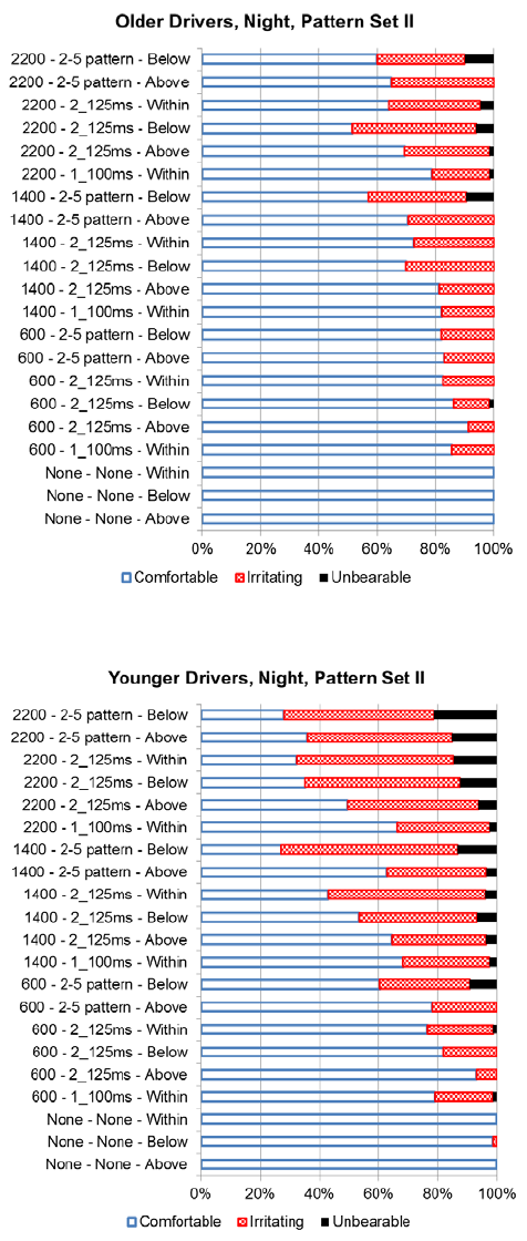
56
Figure 29. Graph. Older driver nighttime discomfort rating for set II.
Figure 30. Graph. Younger driver nighttime discomfort rating for set II.
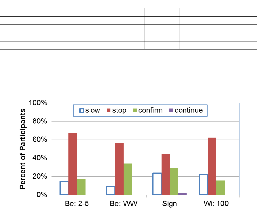
57
Concluding Survey
Queries 1 and 2—Driver Responses
The initial two queries asked the participants to indicate how the driver in the video would react
to the pedestrian attempting to cross at the crosswalk. Table 18 highlights the number of
participants who selected each of the potential responses for both queries 1 and 2 with the
percent of participants shown in parentheses. Figure 31 shows a plot of the findings. For all
of the devices studied, the answer selected by the majority of the participants was “stop.” For
two devices—the wig-wag pattern on the LEDs located below the sign and the sign without any
active LEDs—had about one-third of the participants selecting the “confirm pedestrian is not
crossing” answer while less than 17 percent selected that answer for the other two devices tested.
Stated in another manner, the 2-5 below and the 100 ms within had more correct responses
(“slow” or “stop” and “allow the pedestrian to cross”) than the sign without LEDs or the sign
with the LEDs below in a wig-wag pattern. The multiple flashes within a short time period,
as is present with the 2-5 pattern, may be better at communicating the need to stop for a
yellow device.
Table 18. Results for survey queries 1 and 2.
Flash Pattern
Number of Participants (Percent of Participants)
Slow
a
Stop
b
Confirm
c
Continue
d
Total
Within; 100
7 (22)
20 (63)
5 (16)
0 (0)
32 (100)
Below; wig-wag
3 (9)
18 (56)
11 (34)
0 (0)
32 (100)
Below; 2-5
5 (15)
23 (67)
6 (17)
0 (0)
34 (100)
Sign
23 (23)
44 (45)
29 (30)
2 (2)
98 (100)
a
I would slow and allow the pedestrian to cross the roadway.
b
I would stop and allow the pedestrian to cross the roadway.
c
I would confirm the pedestrian is not crossing before proceeding.
d
I would continue driving at the same speed.
Note: Flash patterns are defined as follows: 100 = one 100-ms flash pattern; wig-wag = wig-wag flash pattern;
2-5 = 2-5 flash pattern; and sign = no active LEDs.
Figure 31. Graph. Results for survey queries 1 and 2.
58
Queries 3 and 4—Flash Pattern and LED Location
Queries 3 and 4 explored whether certain flash patterns and LED locations affected the
participants’ sense of urgency in needing to yield to a pedestrian. Each participant saw two pairs
of videos. The results for queries 3 and 4 were combined for this review along with whether the
sign was shown on the left side or the right side of the screen. To facilitate review of the results,
findings were repeated for each pair combination (e.g., the results were shown for both the
comparison of the within LEDs being on for 100 ms to sign (i.e., no active beacons) as well as
sign (i.e., no active beacons) to within LEDs being on for 100 ms). Table 19 and table 20 show
the results.
Table 19 contains the comparisons between having a sign with no active LEDs and the other
combinations. For all of these comparisons, the majority of the participants selected the device
with an active LED as communicating more urgency for yielding. For the comparison between
sign and either below LEDs with a 2-5 flash pattern or below LEDs with four 25-ms flashes and
one 100-ms flash, all of the participants felt the flashing device communicated a greater urgency
to yield than the sign without an active LED. A majority of the participants (60 percent) felt the
within LEDs with two 125-ms flashes communicated a greater urgency; however, 30 percent felt
that neither device communicated urgency.
Table 19 also shows the results for the comparisons with the devices when the LEDs below
the sign were active. When the 2-5 flash pattern was used with the LEDs below the sign, the
participants felt it communicated a greater urgency as compared to the three patterns tested
with the LEDs within the sign. The 2-5 pattern below the sign was favored by 90 percent of
participants compared to the single 100-ms flash within the sign, by 78 percent compared to
two 125-ms flashes within the sign, and 78 percent compared to four 25-ms flashes and
one 200-ms flash within the sign. The comparison of the 2-5 flash pattern to the flash pattern
with four 25-ms flashes and one 200-ms flash used with the below LEDs showed that the
majority of the participants felt both devices communicated similar urgency (66 percent). The
flash pattern for the below LEDs with four 25-ms flashes and one 200-ms flash was a subset of
the below 2-5 flash pattern in that it was the “5” portion of the 2-5 pattern. Perhaps it was the
multiple pulses that helped to communicate the urgency. The comparison of the 2-5 flash pattern
with the pattern that only had the two pulses (below LEDs with two 125-ms flashes) had fewer
participants feeling that both of these devices communicated a similar urgency (only 33 percent).
This result provides some support that the multiple pulses helped to communicate urgency.
A total of 22 percent of the participants felt the below LEDs with two 125-ms flashes
communicated greater urgency as compared to the below 2-5 flash pattern, which added caution
to the observation that more flashes were associated with greater urgency. The location of the
LEDs may be another factor.
The comparison of the same number of flashes being used at different LEDs locations shows that
participants believed the LEDs below the sign demonstrated more urgency than LEDs within the
sign. For example, when two 125-ms pulses were used, the participants felt the LEDs below
communicated a greater urgency (70 percent). The results for the four 25-ms flashes and
one 200-ms flash also revealed that more participants felt the LEDs below (78 percent) showed
greater urgency.

59
Within the comparisons of different flash patterns used with the within LEDs (see table 20),
almost all of the participants (80 percent) felt the two-pulse pattern (i.e., two 125-ms pulses) and
the five-pulse pattern (i.e., four 25-ms pulses and one 200-ms pulse) communicated the same
urgency. The participants indicated that the two-pulse pattern (56 percent) communicated greater
urgency over the one-pulse pattern (i.e., within LEDs with one 100-ms flash), or they felt those
two patterns communicated a similar urgency (33 percent).
Table 19. Percent of participants who felt a sense of urgency to yield for signs with no
active LEDs and LEDs below the sign.
Device 1
Device 2
Device 1
More
Urgent
(Percent)
Device 2
More
Urgent
(Percent)
Similar
Urgency
Both
Devices
(Percent)
Neither
Device
Conveys
Urgency
(Percent)
Sign
Within; 100
11
56
22
11
Sign
Within; 125(2)
0
60
10
30
Sign
Within; 25(4)+200
11
56
33
0
Sign
Below; 2-5
0
100
0
0
Sign
Below; 125(2)
0
89
11
0
Sign
Below; 25(4)+200
0
100
0
0
Below; 2-5
Within; one 100
90
0
0
10
Below; 2-5
Within; 125(2)
78
0
22
0
Below; 2-5
Within; 25(4)+200
78
0
11
11
Below; 2-5
Below; 125(2)
44
22
33
0
Below; 2-5
Below; 25(4)+200
25
13
63
0
Below; 2-5
Sign
100
0
0
0
Below; 125(2)
Within; one 100
89
0
11
0
Below; 125(2)
Within; 125(2)
70
0
30
0
Below; 125(2)
Within; 25(4)+200
90
0
10
0
Below; 125(2)
Below; 2-5
22
44
33
0
Below; 125(2)
Below; 25(4)+200
20
40
40
0
Below; 125(2)
Sign
89
0
11
0
Below; 25(4)+200
Within; one 100
82
0
18
0
Below; 25(4)+200
Within; 125(2)
89
0
11
0
Below; 25(4)+200
Within; 25(4)+200
78
0
11
11
Below; 25(4)+200
Below; 2-5
13
25
63
0
Below; 25(4)+200
Below; 125(2)
40
20
40
0
Below; 25(4)+200
Sign
100
0
0
0
Note: Flash patterns are defined as follows: 100 = one 100-ms flash pattern; 125(2) = two 125-ms flashes;
25(4)+200 = four 25-ms flashes and one 200-ms flash; 2-5 = 2-5 flash pattern; and sign = no active LEDs.

60
Table 20. Percent of participant results for sense of urgency to yield for LEDs
above the sign.
Device 1
Device 2
Device 1
More
Urgent
(Percent)
Device 2
More
Urgent
(Percent)
Similar
Urgency
Both
Devices
(Percent)
Neither
Device
Conveys
Urgency
(Percent)
Within; 100
Within; 125(2)
11
56
33
0
Within; 100
Within; 25(4)+200
0
22
78
0
Within; 100
Below; 2-5
0
90
0
10
Within; 100
Below; 125(2)
0
89
11
0
Within; 100
Below; 25(4)+200
0
82
18
0
Within; 100
Sign
56
11
22
11
Within; 125(2)
Within; 100
56
11
33
0
Within; 125(2)
Within; 25(4)+200
10
0
80
10
Within; 125(2)
Below; 2-5
0
78
22
0
Within; 125(2)
Below; 125(2)
0
70
30
0
Within; 125(2)
Below; 25(4)+200
0
89
11
0
Within; 125(2)
Sign
60
0
10
30
Within; 25(4)+200
Within; 100
22
0
78
0
Within; 25(4)+200
Within; 125(2)
0
10
80
10
Within; 25(4)+200
Below; 2-5
0
78
11
11
Within; 25(4)+200
Below; 125(2)
0
90
10
0
Within; 25(4)+200
Below; 25(4)+200
0
78
11
11
Within; 25(4)+200
Sign
56
11
33
0
Note: Flash patterns are defined as follows: 100 = one 100-ms flash pattern; 125(2) = two 125-ms flashes;
25(4)+200 = four 25-ms flashes and one 200-ms flash; 2-5 = 2-5 flash pattern; and sign = no active LEDs.
Queries 5 and 6—Number of Pulses
For queries 5 and 6, the participants were asked to indicate how many flashes they could see on
the left side and the right side of an active light bar. The research team used the term “flashes”
rather than “pulses” because it has more common usage for the participants. The correct term
would be pulses because “A flash is a light pulse or a train of light pulses, where a dark interval
of at least 160 ms separates the light pulse or the last pulse of the train of light pulses from the
next pulse or the first pulse of the next train of light pulses.”
(15)
(pg. 4)
The 2-5 flash pattern was used and had five pulses on the left side of the light bar and two pulses
on the right side of the light bar. The frequency and percent of the responses by number of pulses
is listed in table 21. One participant said there were eight flashes on each side. The researcher
who worked with that participant believed the participant was counting the number of unique
LEDs within the beacon rather than counting the number of pulses.
The majority of the participants (77 percent) correctly counted two pulses. A few of the
participants (four) correctly counted five pulses. The majority of the participants (55 percent)
saw three pulses when five pulses were present.
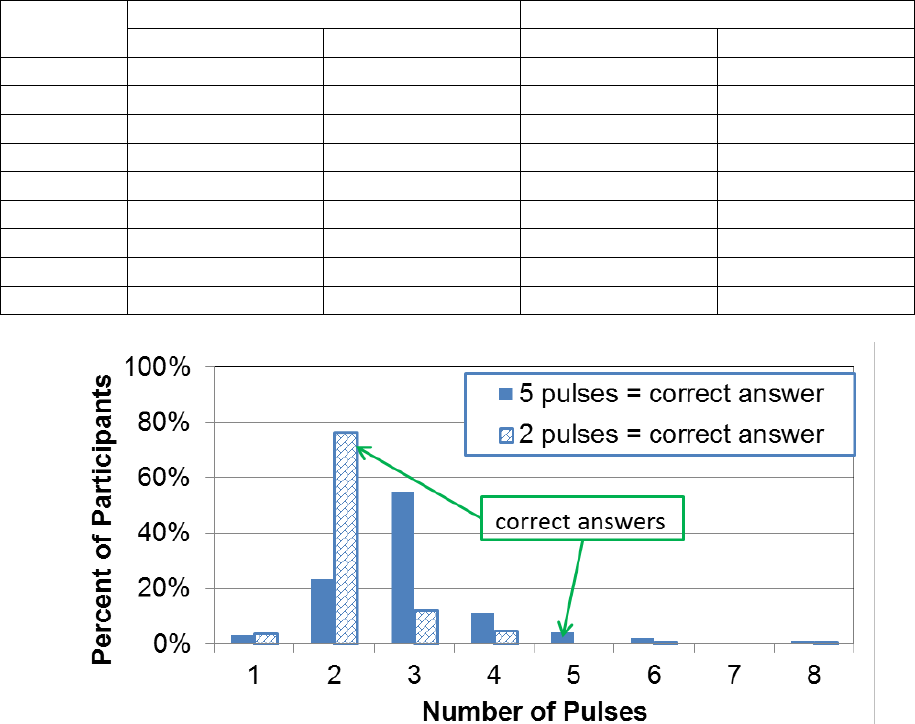
61
Table 21. Number of pulses on light bar.
Number
of Pulses
Response for Side with Five Pulses
Response for Side with Two Pulses
Frequency
Percent
Frequency
Percent
1
3
3
4
4
2
23
23
75
77
3
54
55
12
12
4
11
11
5
5
5
4
4
0
0
6
2
2
1
1
7
0
0
0
0
8
1
1
1
1
Total
98
100
98
100
Figure 32. Graph. Number of pulses by percent of participants.
STATISTICAL ANALYSIS
The following subsections describe the statistical analyses performed on the data collected. It
should be noted that when the term “significant” appears alone in these subsections, it indicates
statistically significant (i.e., the differences found were unlikely to be a random variation
but a systematic, measurable trend). Whenever appropriate, an explicit distinction is made to
differentiate this term from “practical significance,” which refers to the scale of a difference.
For example, a difference may be found statistically significant in one of the analyses, but its
magnitude could be such that is too small to be considered practically significant.
Pedestrian Detection Time
The data were initially split by daytime and nighttime conditions. Each set was analyzed using
linear mixed effects models (LMMs). These kinds of models combine characteristics from
both linear regression and analysis of variance (ANOVA). The model was specified such that
appropriate accounts were given to the data structure, known associations between variables, and
systematic variation in the response variable. The analysis treated the codependency of data
points from the same drivers including a random effect for each participant in the experiment.
62
The analysis incorporated fixed effects for other variables of interest. In the case of detection
time, the fixed effect variables were age, intensity, flash pattern, pedestrian height, and
pedestrian position. Estimates, confidence intervals, and conclusions were later extracted for
these effects. Due to the heavy skewness of the data, the analysis was performed over the natural
logarithm of the detection time (see figure 33).
Figure 33. Equation. Natural logarithm of detection time.
Where:
ln(Detection_Time
i
) = Natural logarithm of detection time for experiment i.
X
i
= Vector of variable levels for experiment i.
= Vector of coefficients for all variables in experiment (fixed effects, estimated).
= Random effect for participant j (estimated).
= Residual error for experiment i and subject j.
This statistical specification with a logged response allowed researchers to make inferences
about the median detection time instead of the mean detection time. Because a logarithm
transformation affects the distribution of the residual errors, the transformed mean is not equal to
the original mean. However, an analysis on the transformed mean is equivalent to analyzing the
median of the original scale (i.e., detection time) as long as normality or near-normality is
achieved after the transformation. This is so because the normal distribution is symmetrical
and also because the quartile distribution of the data is not affected by the log transformation.
Therefore, each coefficient in the vector can be interpreted (after exponentiation) as a
multiplicative change on the median detection time per unit of explanatory variable.
All statistical analyses were performed using open-source statistical software. (See
references 42–45.)
Daytime Time to Detect Pedestrian Direction
Table 22 shows the ANOVA on the variables in this analysis. These results indicate that target
intensity had an impact on the detection time after accounting for the rest of variables in the
table. In fact, except for two variables (LED location and lane) all of the experimental factors
had a significant impact on detection time. The variables used in the following tables are defined
as follows:
• Target intensity: Intensity of LEDs (0, 600, 1,400, or 2,200 candelas).
• Flash pattern: LED flash pattern (none, 2-5 flash pattern, wig-wag, one 100-ms flash, or
five pulses).
• LED location: Location of LEDs in the assembly (above sign, below sign, or
within sign).
• Pedestrian height: Height of the pedestrian when present (tall or short).
lnDetection_Time
i
= X
i
× β + α
j
+ ϵ
ij
β
α
j
ϵ
ij
β

63
• Pedestrian position: Pedestrian position on crosswalk, when present (center, left,
or right).
• Lane: Lane of vehicle with participant (left or right).
• Age: Age of participant (ranging from 19 to 85 years old).
Table 22. Daytime ANOVA for detection time fixed effects.
Variable
Numerator Degrees
of Freedom (DF)
Denominator
DF
F-value
p-value
Reference
1
2956
10730.10
< 0.0001
Target intensity
1
2956
22.44
< 0.0001
Flash pattern
4
2956
4.74
0.0008
LED location
2
2956
0.85
0.4270
Pedestrian height
1
2956
19.59
< 0.0001
Pedestrian position
3
2956
95.61
< 0.0001
Lane
1
28
2.11
0.1571
Age
1
28
7.37
0.0112
The coefficient estimates for daytime are shown in table 23. The comparison of flash patterns
shows that 2-5 flash pattern produced longer detection times, though the p-values should be
adjusted for multiple comparisons. The reference levels used for the base model in this study
were no flash pattern, LED location is above, pedestrian height is tall, pedestrian position is
none, and lane is left. The coefficient for target intensity in table 23 is small and statistically
insignificant. The trend, however, is positive as is the trend at night (discussed in following
subsection). Therefore, the no significance could be explained by the effect being smaller than
the statistical power in the study. Indeed, examining the magnitude of the effect this coefficient
implies, all other factors held equal (i.e. flash pattern, LED location in assembly, pedestrian
height, pedestrian position, lane, and age of participant), the median response time increased by
0.00114 percent per additional candela of intensity (i.e., exp(0.0000114) = 1.0000114), which is
about one-fourth of the magnitude of the same trend at night.

64
Table 23. Daytime detection time fixed effects coefficients.
Coefficient
Value
Standard Error
DF
t-value
p-value
Reference
a
6.39000
0.21700
2956
29.5039
< 0.0001
Target intensity
0.00001
0.00001
2956
1.6846
0.0922
Flash
pattern
2-5
0.05040
0.01800
2956
2.8054
0.0051
b
100
0.04340
0.02380
2956
1.8231
0.0684
b
Five flashes
0.04320
0.02380
2956
1.8135
0.0699
b
Wig-wag
0.02260
0.01800
2956
1.2548
0.2097
b
LED
location
Below
0.00686
0.01000
2956
0.6850
0.4934
b
Within
-0.00422
0.02370
2956
-0.1783
0.8585
b
Pedestrian height—short
0.03850
0.00825
2956
4.6637
< 0.0001
Pedestrian
position
Center
-0.22200
0.01320
2956
-16.8046
< 0.0001
b
Left
-0.16700
0.01320
2956
-12.6137
< 0.0001
b
Right
-0.16400
0.01330
2956
-12.3883
< 0.0001
b
Lane—right
0.17300
0.13400
28
1.2902
0.2075
Age
0.00947
0.00349
28
2.7139
0.0112
a
Reference level used in model for each categorical variable base value: flash pattern = sign, LED location = above,
pedestrian height = tall, pedestrian position = no pedestrian, and lane = left.
b
p-values for discrete factors with three or more levels need a multiple comparison adjustment.
Note: Flash patterns are defined as follows: 2-5 = 2-5 flash pattern; 100 = one 100-ms flash pattern; and wig-wag =
wig-wag flash pattern.
The adjusted comparisons, shown in table 24, constitute evidence of the 2-5 flash pattern being
the only flash pattern with statistically significantly longer detection times than no LEDs flashing
during daytime conditions.
Table 24. Daytime simultaneous tests for general linear hypothesis of detection time flash
pattern effects.
Condition 1
Condition 2
Estimate
a
Standard
Error
z-value
p-value
b
Significance
c
2-5 flash pattern
None
0.05037
0.01796
2.805
0.0175
*
Wig-wag
None
0.02264
0.01805
1.254
0.5029
One 100-ms flash
None
0.04337
0.02379
1.823
0.1952
Five flashes
None
0.04323
0.02384
1.813
0.1986
a
Estimate is the difference between fixed effects coefficients corresponding to conditions 1 and 2.
b
Adjusted p-values were reported using a single-step method.
c
Significance values are as follows: blank cell = p > 0.10; ~ = p < 0.10; * = p < 0.05; ** = p < 0.01; and
*** = p < .0.001.
Each row in in table 24 represents a scientific hypothesis being tested statistically from the
model results. For example, the first row of this table corresponds to the hypothesis that the
natural logarithm of the average detection time under the 2-5 flash pattern is no different from
the natural logarithm of the detection time when no flashing is present. The estimate for the
difference of natural logarithm of detection time under each of these conditions is shown under
the column titled “Estimate.” The last four columns provide the basis for the assessment of the
statistical significance of said difference in natural logarithm of detection time.

65
For the four intensity levels used in the study, table 25 shows that the magnitude of the intensity
effect on median detection time is negligible during the daytime.
Table 25. Daytime magnitude of detection time intensity effect.
Target Intensity
(Candela)
Estimated Increase in Median
Detection Time (Percent)
0
0 (reference level)
600
0.7
1,400
1.6
2,200
2.4
There was a moderate impact of pedestrian height in detection time. Using the corresponding
coefficient in table 23, results indicate that there was a 3.9 percent increase in detection time
when using a short pedestrian cutout instead of a tall pedestrian cutout.
Nighttime Time to Detect Pedestrian Direction
Table 26 shows the ANOVA on the variables of interest. The results indicate that at night, all of
the experimental factors had a significant impact on detection time except for lane.
Regarding flash patterns, the 2-5 flash pattern is again the pattern that triggered longer detection
times. For nighttime, wig-wag was also associated with longer detection times.
Table 26. Nighttime ANOVA for detection time fixed effects.
Variable
Numerator DF
Denominator DF
F-value
p-value
Reference
1
6,016
39772.22
< 0.0001
Target intensity
1
6,016
85.61
< 0.0001
Flash pattern
5
6,016
30.74
< 0.0001
LED location
2
6,016
73.12
< 0.0001
Pedestrian height
1
6,016
22.06
< 0.0001
Pedestrian position
3
6,016
149.86
< 0.0001
Lane
1
60
1.46
0.2322
Age
1
60
8.74
0.0045

66
The coefficient estimates for nighttime are shown in table 27.
Table 27. Nighttime fixed effects coefficients for detection time.
Coefficient
Value
Standard Error
DF
t-value
p-value
Reference
a
6.6900
0.1060
6,016
63.2133
0.0000
Target intensity
0.0000
0.0000
6,016
5.9727
0.0000
Flash
pattern
2-5
0.0580
0.0154
6,016
3.7787
< 0.00
b
100
-0.0328
0.0184
6,016
-1.7841
0.0745
b
125(2)
-0.0077
0.0162
6,016
-0.4770
0.6330
b
Five pulses
-0.0172
0.0213
6,016
-0.8106
0.4180
b
Wig-wag
0.1280
0.0175
6,016
7.3196
< 0.001
b
LED
location
Below
0.1160
0.0091
6,016
12.7706
< 0.001
b
Within
0.0582
0.0139
6,016
4.1920
< 0.001
b
Pedestrian height—short
0.0357
0.0075
6,016
4.7693
0.0000
Pedestrian
position
Center
-0.1310
0.0118
6,016
-11.1563
< 0.001
b
Left
0.0490
0.0119
6,016
4.1094
< 0.001
b
Right
0.0465
0.0119
6,016
3.9206
< 0.001
b
Lane—right
0.0950
0.0717
60
1.3252
0.1900
Age
0.0056
0.0019
60
2.9558
0.0045
a
Reference level used in model for each categorical variable base value: flash pattern = sign, LED location =
above, pedestrian height = tall, pedestrian position = no pedestrian, and lane = left.
b
p-values for discrete factors with three or more levels need a multiple comparison adjustment.
Note: Flash patterns are defined as follows: 2-5 = 2-5 flash pattern; 100 = one 100-ms flash pattern; 125(2) =
two 125-ms flashes; and wig-wag = wig-wag flash pattern.
Table 28 shows the differences among flash patterns with statistical significance adjusted for
multiple comparisons.
Table 28. Nighttime simultaneous tests for general linear hypothesis of flash patterns on
detection time.
Condition 1
Condition 2
Estimate
a
Standard
Error
z-value
p-value
b
Significance
c
2-5 flash pattern
None
0.058007
0.015354
3.778
< 0.001
***
Wig-wag
None
0.12806
0.017492
7.321
< 0.001
***
One 100-ms flash
None
-0.03284
0.018403
-1.784
0.248
Two 125-ms flashes
None
-0.00776
0.016156
-0.48
0.983
Five pulses
None
-0.0172
0.021267
-0.809
0.871
a
Estimate is the difference between fixed effects coefficients corresponding to conditions 1 and 2.
b
Adjusted p-values were reported using a single-step method.
c
Significance values are as follows: blank cell = p > 0.10; ~ = p < 0.10; * = p < 0.05; ** = p < 0.01; and *** = p < 0.001.
There was statistical evidence of the 2-5 flash pattern delaying detection. The magnitude of this
delay was very similar to the daytime delay (6 percent increase in median detection time at night
versus 5.2 percent at daytime). However, at night, there was also evidence that the wig-wag flash
pattern also delayed pedestrian detection. This delay is a substantial increase in detection time.
Other variables being equal, median detection time was 13.7 percent longer for the wig-wag

67
pattern than the median detection time with no LEDs active (i.e., 13.7 percent=[exp(0.12806) –
1.0] × 100 percent).
The coefficient for target intensity at night was highly significant as opposed to being
insignificant during the daytime. This coefficient was also larger at night by a factor of about 3.7
compared to the daytime. It is estimated that the median response time increased by
0.00369 percent per additional candela of intensity (i.e., exp(0.0000369) = 1.0000369) after
controlling for other experimental factors. Table 29 shows the magnitude of the estimated impact
of LED intensity. These magnitudes were substantial increases in median detection time.
Table 29. Nighttime magnitude of intensity effect on detection time.
Target Intensity
(Candela)
Estimated Increase in Median
Detection Time (Percent)
0
0.0 (reference level)
600
2.2
1,400
5.3
2,200
8.5
There was a moderate impact of pedestrian height on detection time. Using the coefficient in
table 27, results indicate that there was a 3.6 percent increase in detection time when using a
short pedestrian cutout instead of a tall pedestrian cutout.
Table 30 shows the relative effects of LED location with statistical significance adjusted for
simultaneous comparisons. The shortest nighttime detection times occurred when the LEDs were
located above the sign. Using this position as a reference level, the median detection time was
6 percent longer when the LEDs were located within the sign and 12.3 percent longer when the
LEDs were located below the sign as compared to above. Finally, a comparison between LEDs
within the sign against LEDs below the sign indicated that the median detection time was
6 percent longer at LEDs below the sign. All three contrasts were statistically significant.
Table 31 summarizes these findings.
Table 30. Nighttime simultaneous tests for effect of LED location on detection time.
Condition 1
Condition 2
Estimate
a
Standard
Error
z-value
p-value
b
Significance
c
Below
Above
0.116373
0.009112
12.771
< 0.001
***
Within
Above
0.058172
0.013877
4.192
< 0.001
***
Below
Within
0.058202
0.013906
4.185
< 0.001
***
a
Estimate is the difference between fixed effects coefficients corresponding to conditions 1 and 2.
b
Adjusted p-values were reported using a single-step method.
c
Significance values are as follows: blank cell = p > 0.10; ~ = p < 0.10; * = p < 0.05; ** = p < 0.01; and *** = p < 0.001.
Table 31. Nighttime magnitude of LED location effect on detection time.
LED Location
Estimated Increase in Median
Detection Time (Percent)
Above
0.0 (reference level)
Within
6.0
Below
12.3
68
Key Findings Regarding Detection Time
For the analysis focusing on detection time, (i.e., the time it took participants to indicate the
direction of the cutout pedestrian from the moment the occlusion glasses were cleared), results
indicate the following:
• As expected, detection time was longer at night than during the day.
• The age of the participants had an impact on detection time, both during the day and at
night. Detection time for younger participants was shorter than detection time for older
participants. It is estimated that there was an increase of 1 percent in median detection
time per year of age during the daytime. At night, age made less of a difference. The
corresponding estimate for this effect was an increase of 0.5 percent in median detection
time per year of age.
• Pedestrian height had a very similar impact on detection time during the day and at night.
Detection time was longer when the pedestrian cutout was short rather than tall. Results
indicate an increase in median detection time of 3.9 percent during the daytime and an
increase of 3.6 percent at night for the short pedestrian cutout compared to a tall cutout.
• In the case of pedestrian position, trends were the same for daytime and nighttime:
detection times were longer when the pedestrian cutout was located on either side of the
crosswalk compared to when it was located at the center of the road.
• Flash pattern also had a significant impact on detection time, though most of the
differences between the different flash patterns were not statistically significant. Only
two flash patterns produced significantly longer detection times than the base level of no
flash pattern: the 2-5 flash pattern (used above and below sign) used during the day and at
night and the wig-wag pattern (used above and below sign) at night only. Compared to no
active flash pattern, there was an increase in median detection time for the 2-5 flash
pattern by 5.2 percent during the day and of 6 percent at night. The wig-wag pattern
caused an increase in median detection time of 13.7 percent.
LED location had a significant impact at night but not during the day. At night, detection was
fastest when the LEDs were above the signs after controlling for other factors. Compared to the
above sign LED location, the median detection time increased by 6 percent when the LEDs were
within the sign and increased by an additional 6 percent when the LEDs were below the sign for
a total increase of 12.3 percent when the below location was compared to the above location.
Accuracy of Detecting Pedestrian Direction
Similar to the analysis of detection time, the data were split by daytime and nighttime conditions.
In the detection time analysis, only data representing the correct responses by the participant
were utilized. For the accuracy analysis; however, the dataset also included the instances when
participants indicated the incorrect walking direction. This analysis used both subsets (i.e.,
correct and incorrect answers) to evaluate changes in the rate of correct to total answers due to
the different variables considered in the experimental design.
69
The analysis of the resulting dataset was performed on the framework of generalized linear
mixed effects models (GLMMs). Similarly to LMMs, these kinds of models combine
characteristics from both generalized linear regression and analysis of deviance. The analysis
treated the co-dependency of data points from the same drivers including a random effect for
each participant in the experiment. In doing so, the model gave an appropriate account to the
correlation structure in the data. The model also included a simultaneous parametric estimation
for the variables of interest (i.e., as fixed effects).
Similar to the analysis of detection time, the fixed effect variables were age, intensity, flash
pattern, pedestrian height, and pedestrian position. Estimates, confidence intervals, and
conclusions were later extracted for these effects. The formal specification of the statistical
model for accuracy analysis is shown in figure 34.
Figure 34. Equation. Accuracy analysis.
Where:
Logit = Logit transformation, such that Logit(x) = Ln[x/(1 − x)].
Accuracy_Rate
ij
= Accuracy rate at experiment i for participant j.
X'
ik
= Vector of k variables whose levels are set for experiment i.
Since each experiment was only recorded once per participant, the best estimator for the
accuracy rate was a binary variable, Z, representing the outcome of 1 if the response was correct,
0 otherwise. This variable was utilized as the response in the analysis. To make this a statistical
model, an assumption that Z was binomially distributed was made, as shown in figure 35.
Figure 35. Equation. Accuracy rate.
The accuracy rate in the equation shown in figure 30 was estimated in the model. The known
parameter n is the number of valid data points for each experiment/participant combination,
which equals 1 in this study. The experiment design was such that only one response was
obtained per experiment/participant combination. The model is then as shown in figure 36.
Figure 36. Equation. Logit model.
Where:
X' = Vector of explanatory variables.
= Random effect, estimated for each participant.
The variables and in the equation shown in figure 36 were estimated by maximum
likelihood.
LogitAccuracy_Rate
ij
= X'
ik
× β + α
j
Z~Binomial
(
Accuracy_Rate, n = 1
)
Logit
(
Z
)
= X' × β + α
α
β
α

70
Model Interpretation
The statistical specification linked the logit of the accuracy rate to a linear combination of the
factors in the experiment design. Because the logit transformation is the natural logarithm of the
odds of correct responses, inferences about the impact of changing experimental factors X to the
accuracy rate should be made as follows: a marginal change of one variable in the linear
predictor represents a multiplicative change in the odds of participant j correctly identifying
the pedestrian direction. For experimental factor X
i1
, with two levels, A and B, the equation in
figure 37 defines the odds ratio that corresponds to coefficient, .
Figure 37. Equation. Odds ratio corresponding to levels A and B of factor X
i
1
.
Where:
= Odds of level A of factor x
i1
.
= Odds of level B of factor x
i1
.
The equation in figure 37 indicates that the odds ratio (i.e., the ratio of odds of correct answers at
level A to odds of correct answers at level B) is the exponential of the difference between levels
multiplied by the corresponding regression coefficient. All statistical analyses were performed
using R, an open-source statistical software. (See references 42–45.)
Daytime Accuracy of Detecting Pedestrian Direction
Table 32 shows the proportion of deviance corresponding by each variable in the analysis (i.e.,
analogous to an ANOVA table). This table indicates that target intensity had little or no impact
on accuracy after accounting for the rest of the variables in the experiment design. Similarly,
flash pattern did not have any influence on the odds of correctly detecting the pedestrian cutout.
In contrast, this table shows that pedestrian position and participant age were the only
two variables that were influential to accuracy of pedestrian detection. Specific coefficient
estimates for daytime are shown in table 33.
Table 32. Daytime analysis of deviance for accuracy fixed effects.
Variables
Numerator DF
Sum of Squares
Mean Squares
F-value
p-value
a
Target intensity
1
0.812
0.812
0.812
0.367
Flash pattern
4
5.266
1.316
1.316
0.261
LED location
2
1.370
0.685
0.685
0.504
Pedestrian height
1
1.934
1.934
1.934
0.164
Pedestrian position
3
10.004
3.335
3.335
0.019
Lane
1
1.230
1.230
1.230
0.267
Age
1
12.130
12.130
12.130
< 0.001
a
The statistics in this table are based on maximum likelihood estimates convergence to normality by virtue of the law of
large numbers. Therefore, p-values were obtained from the limit case when DF in the denominator tends to infinity.
In table 33, only two coefficients were statistically significant: age of the participants and the
position of the cutout when it faced to the right. The coefficient for age indicates that there was
β
1
exp β
1
×
(
A − B
)
=
ω
x
i1 = A
ω
x
i1
= B
ω
x
i1
=
ω
x
i1
=

71
an inverse relationship between age and accuracy, as was expected. Except for the variables
explicitly depicted, the rates in figure 38 correspond to the reference levels listed in table 33.
From figure 38, it is evident that accuracy at daytime was high in general, with about 3 percent
reduction in accuracy rates for the oldest participants when compared to the youngest
participants in the study.
For the second statistically significant variable (i.e., pedestrian position to the right), the
three p-values in table 33 should be adjusted for multiple comparisons. Table 34 shows multiple
comparisons of interest and corresponding adjusted p-values. Although the trends are similar
when comparing left and right sides with the center position, only the comparison between right
side and center positions offers suggestive evidence of a real difference.
Table 33. Daytime accuracy fixed effects coefficients.
Daytime Coefficients
Value
Standard
Error
z-value
p-value
Reference
a
9.5480
1.3160
7.258
< 0.001
Target intensity
0.0004
0.0002
1.640
0.101
Flash pattern
2-5
-0.5800
0.6180
-0.938
0.34
b
100
-1.2440
1.1540
-1.079
0.281
b
Five flashes
-0.2500
1.2490
-0.200
0.841
b
Wig-wag
-0.9990
0.6120
-1.631
0.103
b
LED location
Below
-0.3600
0.3320
-1.085
0.278
b
Within
0.2380
1.1790
0.202
0.840
b
Pedestrian height—short
-0.4350
0.2990
-1.453
0.146
Pedestrian
position
Center
-0.8780
0.8170
-1.075
0.282
b
Left
-1.5140
0.7840
-1.931
0.054
b
Right
-1.8500
0.7730
-2.391
0.017
b
Lane—right
-0.3470
0.4520
-0.768
0.442
Age
-0.0490
0.0140
-3.483
< 0.001
a
Reference level used in model for each categorical variable base value: flash pattern = sign, LED
location = above, pedestrian height = tall, pedestrian position = no pedestrian, and lane = left.
b
p-values for discrete factors with three or more levels need a multiple comparison adjustment.
Note: Flash patterns are defined as follows: 2-5 = 2-5 flash pattern; 100 = one 100-ms flash pattern; and
wig-wag = wig-wag flash pattern.
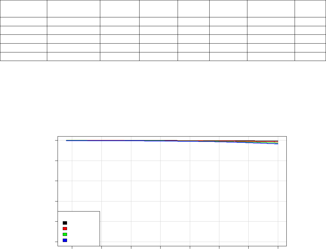
72
Table 34. Daytime simultaneous tests for general linear hypothesis of flash pattern
accuracy effects.
Condition 1
Condition 2
Estimate
a
Standard
Error
z-value
Pr (> |z|)
b
Significance
c
Odds
Ratio
Center
No pedestrian
-0.878
0.817
-1.075
0.6516
0.416
Left Side
Center
-0.636
0.419
-1.520
0.3660
0.529
Right Side
Center
-0.972
0.399
-2.438
0.0534
~
0.378
Both Sides
Center
-0.804
0.3735
-2.153
0.1073
0.448
Left Side
Right Side
0.3355
0.3324
1.009
0.6948
1.399
a
Estimate is the difference between fixed effects coefficients corresponding to conditions 1 and 2.
b
Adjusted p-values were reported using a single-step method.
c
Significance values are as follows: blank cell = p > 0.10; ~ = p < 0.10; * = p < 0.05; ** = p < 0.01; and *** = p < 0.001.
Figure 38 and figure 39 show accuracy rates by pedestrian cutout position and age after
accounting for other experimental factors. The extreme difference in accuracy curves when the
pedestrian cutout is present is between the center and right-side positions as shown in figure 39.
This difference was negligible for younger drivers and was a modest 3 percent for older drivers.
Figure 38. Graph. Daytime estimated accuracy rate by age and pedestrian position.
20 30
40
50 60 70 80 90
0 20 40 60 80 100
Age (years of age)
Accuracy Rate (%)
Ped Position
None
Center
Left-Side
Right-Side
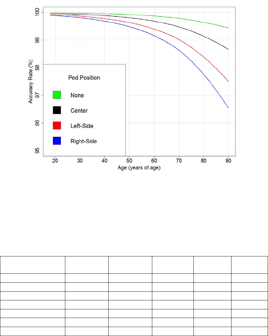
73
Figure 39. Graph. Close-up view of daytime estimated accuracy rate by age and pedestrian
position.
Nighttime Accuracy of Detecting Pedestrian Direction
Table 35 shows the analysis of deviance of the model in this analysis. These results indicate that
at night, all the experimental factors have a significant impact on the accuracy rate, except for
lane. The coefficient estimates for nighttime are shown in table 36.
Table 35. Nighttime analysis of deviance for accuracy fixed effects.
Variables
Numerator
DF
Sum of
Squares
Mean
Squares
F-value
p-value
a
Target intensity
1
14.174
14.174
14.174
< 0.001
Flash pattern
5
13.470
2.694
2.694
0.019
LED location
2
50.289
25.145
25.145
< 0.001
Pedestrian height
1
15.686
15.686
15.686
< 0.001
Pedestrian position
3
95.724
31.908
31.908
< 0.001
Lane
1
1.363
1.363
1.363
0.243
Age
1
11.166
11.166
11.166
< 0.001
a
The statistical quantifiers in this table are based on maximum likelihood estimates convergence to normality
by virtue of the law of large numbers. Therefore, p-values were calculated in the limit when DF in the
denominator tended to infinity.

74
Table 36. Nighttime accuracy fixed effects coefficients.
Nighttime Coefficients
Value
Standard
Error
t-value
p-value
Reference
a
8.2800
0.6580
12.575
< 0.0001
Target intensity
-0.0003
0.0001
-2.789
0.0053
Flash pattern
2-5
-0.2810
0.2440
-1.149
0.2506
b
100
0.3250
0.3020
1.073
0.2831
b
125(2)
0.2070
0.2590
0.802
0.4223
b
Five flashes
0.1160
0.3430
0.338
0.7357
b
Wig-wag
-0.4010
0.2750
-1.458
0.1447
b
LED
location
Below
-1.0900
0.1410
-7.762
< 0.0001
b
Within
-0.7780
0.2320
-3.349
0.0008
b
Pedestrian height—short
-0.4540
0.1160
-3.918
0.0001
Pedestrian
position
Center
-1.8900
0.4090
-4.625
< 0.0001
b
Left
-2.9200
0.4000
-7.305
0.0000
b
Right
-2.8400
0.4010
-7.101
0.0000
b
Lane—right
0.3300
0.3200
1.031
0.3025
Age
-0.0283
0.0085
-3.342
0.0008
a
Reference level used in model for each categorical variable base value: flash pattern = sign, LED
location = above, pedestrian height = tall, pedestrian position = no pedestrian, and lane = left.
b
p-values for discrete factors with three or more levels need a multiple comparison adjustment.
Note: Flash patterns are defined as follows: 2-5 = 2-5 flash pattern; 100 = one 100-ms flash pattern;
125(2) = two 125-ms flashes; and wig-wag = wig-wag flash pattern.
There was no evidence of a difference in accuracy of answers due to different flash patterns after
accounting for other relevant factors. Compared to the no flash pattern, only the 2-5 and wig-wag
flash patterns seemed to have hindered accuracy (i.e., negative coefficients), but the data did
not offer statistical evidence that these differences in fact diverged from zero. However, it is
interesting that these two flash patterns were the same for which the analysis of detection time
found evidence of being counterproductive.
Also, similar to the results of the detection time analysis, the accuracy analysis found that
intensity of the LEDs had an adverse effect. Using the base conditions from table 36, figure 40
and figure 41 demonstrate in absolute terms the impact of target intensity across the range of
ages of participants. Also shown in figure 41 is the significant impact of participant age in
accuracy of detection. Table 37 shows the odds ratios for the four intensity levels in this study.
This table demonstrates that the odds of correct detections fell with increasing intensity.
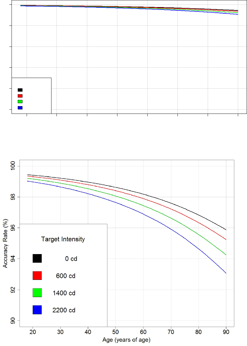
75
Figure 40. Graph. Nighttime estimated accuracy rate by age and LED intensity.
Figure 41. Graph. Close-up view of nighttime estimated accuracy rate by age and LED
intensity.
20 30 40 50 60 70
80
90
0 20 40 60 80 100
Age (years of age)
Accuracy Rate (%)
Target Intensity
0 cd
600 cd
1400 cd
2200 cd

76
Table 37. Nighttime odds ratio of correct detection intensity levels.
Target Intensity
(Candela)
Odds Ratio
(Correct Detections)
0
1.00 (reference level)
600
0.86
1,400
0.71
2,200
0.58
Table 38 shows the relative effects of pedestrian location with statistical significance adjusted for
simultaneous comparisons. Compared to pedestrian in the center of the crosswalk, placing the
pedestrian on either side caused a significant drop in the odds of accurate answers. The
difference between left and right sides was found to be not significant.
Table 38. Nighttime simultaneous linear hypotheses for pedestrian position effect on
accuracy.
Condition 1
Condition 2
Estimate
a
Standard
Error
z-value
Pr( >|z|)
b
Significance
c
Odds
Ratio
Center
No pedestrian
-1.88952
0.40859
-4.625
< 0.001
***
0.151
Left side
Center
-1.03111
0.15249
-6.762
< 0.001
***
0.357
Right side
Center
-0.95434
0.15456
-6.175
< 0.001
***
0.385
Both sides
Center
-0.99272
0.13994
-7.094
< 0.001
***
0.371
Left side
Right side
-0.07677
0.12629
-0.608
0.914
0.926
a
Estimate is the difference between fixed effects coefficients corresponding to conditions 1 and 2.
b
Adjusted p-values were reported using a single-step method.
c
Significance values are as follows: blank cell = p > 0.10; ~ = p < 0.10; * = p < 0.05; ** = p < 0.01; and *** = p < 0.001.
Table 39 shows the relative effects of LED location with statistical significance adjusted for
simultaneous comparisons. The most accurate detections at night occurred, as well as the shortest
detection times, when the LEDs were located above the sign. Other variables kept equal, the
odds of accurate detection with LEDs below the sign were about one-third of the odds with
LEDs above sign. The data did not provide evidence supporting any significant difference in
odds of accurate detection when comparing LEDs located below and within the sign.
Table 39. Nighttime simultaneous linear hypotheses on LED location effect on accuracy.
Condition 1
Condition 2
Estimate
a
Standard
Error
z-value
Pr( >|z|)
b
Significance
c
Odds
Ratio
Below
Above
-1.0943
0.141
-7.762
< 0.001
***
0.335
Within
Above
-0.7783
0.2324
-3.349
0.00206
0.459
Below
Within
-0.316
0.2161
-1.462
0.30099
0.729
a
Estimate is the difference between fixed effects coefficients corresponding to conditions 1 and 2.
b
Adjusted p-values were reported using a single-step method.
c
Significance values are as follows: blank cell = p > 0.10; ~ = p < 0.10; * = p < 0.05; ** = p < 0.01; and *** = p < 0.001.
Key Findings Regarding Accuracy of Detection
For the analysis focusing on accuracy of detection, results indicate the following:
• As expected, detection accuracy was higher during the daytime than at night.
77
• The age of participants had an impact on accuracy, both during the daytime and at night.
Accuracy at daytime was high in general. The analysis indicated, however, a measurable
but small reduction in accuracy by age. For example, it was estimated that there was a
difference of about 3 percent in accuracy rate between the oldest participants (85 years
old) and the youngest participants (19 years old) when they were presented with no
flashing LEDs and the tall pedestrian was placed at either the right or the left side.
Similarly, the age of the participant had a significantly larger effect under nighttime
conditions compared to daytime conditions. For the same scenario described (i.e., no
LED and the tall pedestrian cutout positioned at either the right or the left side of the
crosswalk) the difference between accuracy rates of a participant 85 years old and
another participant 19 years old was estimated at about 8 percent.
• Regarding pedestrian height, accuracy was higher when the pedestrian cutout was tall
compared to when it was short.
• Pedestrian position had an impact on accuracy. The evidence for this effect was strong at
night but only suggestive during the daytime. In general, locating the pedestrian at the
center of the crosswalk had more accurate responses compared to when the cutout was
located at either side of the crosswalk. In particular for daytime, only the difference
between right-side and center position had a statistical significance, and it was minimal.
For nighttime, however, the trends were the same, but the data provided convincing
evidence of an impact of pedestrian position: lower accuracy could be attributed to
placing the pedestrian cutout on either side of the crosswalk (i.e., closer to the LED
assembly) compared to the center position. This finding suggests that being further away
from the active LEDs makes accurately detecting pedestrian walking direction easier. As
with daytime, no statistical difference was found between the left and right sides at night.
• No evidence was found of the flash pattern having a significant impact on accuracy
during the day and at night.
• LED location had a significant impact on accuracy at night but not during the day. At
night, detection was most accurate when the LEDs were above the signs after controlling
for other factors. Placing the LEDs within the sign led to slightly better accuracy rates
than the below location, which was similar to the trends observed for detection time
across LED locations. However, this small difference in accuracy rates was not found
statistically significant.
Discomfort Glare
The discomfort data obtained from participants’ responses were categorized by daytime and
nighttime conditions for the analysis. Similar to the analysis of detection times, the only
discomfort data used in the analysis were those provided after a correct response was given
on pedestrian direction. The discomfort analysis statistically evaluated the changes in the
expressed discomfort that could be attributed to the different variables considered in the
experimental design.
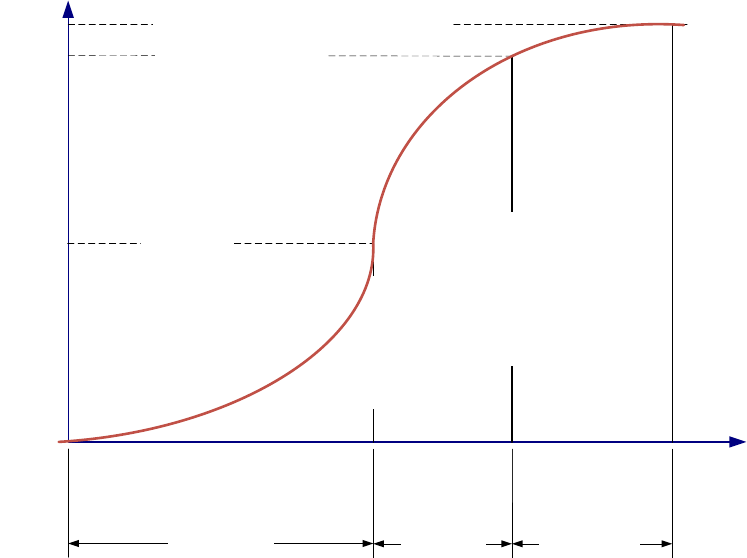
78
The analysis used GLMMs to account for repeated measures taken from the same participants.
Similar to the previous two analyses, variables age, intensity, flash pattern, pedestrian height,
and pedestrian position were coded as fixed effects, with their corresponding standard errors and
confidence intervals. Random intercepts per participant were included as a random effect to
induce the correlation expected between all responses from each participant.
The discomfort level expressed by the participants could be described as a discrete partition of
a continuous non-observable variable that indicated true discomfort. In other words, the true
discomfort experienced was ideally a continuous, monotonic function. The goal of the analysis
was, in essence, to characterize the relationship between the unobserved real discomfort and
the three-level, discrete variable corresponding to the question asked to participants after each
experiment (where the only possible answers were comfortable, irritating, and unbearable).
The relationship between the true and discrete discomfort variables can be idealized by the plot
shown in figure 42 for a given level of an experimental factor:
Figure 42. Graph. Idealized relationship between discrete and real discomfort scales.
It can be logically concluded from this graph that the cumulative frequency of answers from all
participants defines incremental thresholds in the real discomfort level. Therefore, the statistical
analysis quantified how the thresholds changed in response to the variability of the factors in the
experiment design. These changes should directly correspond to changes in the idealized
continuous discomfort scale.
Given that the odds corresponding to the cumulative frequency at any of the two thresholds are
proportional to the odds corresponding to the cumulative frequency at the other threshold, then
Cumulative Frequency
Real Discomfort Level
P(‘comfortable’)+P(‘Irritating’)
P(‘comfortable’)
P(‘comfortable’)+P(‘irritating’) +P(‘unbearable’) = 1.0
Irritating threshold
Comfortable range
Irritating range
Unbearable range
Unbearable threshold
79
any of these cumulative frequencies can be related to the explanatory factors, as shown in
figure 43.
Figure 43. Equation. Cumulative frequency.
Where:
Cumulative_frequency
dij
= Cumulative frequency of answers below threshold d in the discretized
scale of discomfort at experiment i for participant j.
= Log-odds of the threshold for discomfort level d at base conditions (estimated).
Model Interpretation
The statistical specification linked the logit of the cumulative rate in the discomfort scale to a
linear combination of the factors in the experiment design. Because the logit transformation is
the natural logarithm of the odds, inferences about the impact of changing experimental factors X
to the discomfort rate cannot be made in a linear fashion. Instead, inferences should be made
similar to interpreting a logistic model as follows: for a given threshold d, a positive marginal
change of one variable in the linear predictor represents a multiplicative increase in the odds of
the participant indicating any higher level of discomfort compared to the odds of any lower level
of discomfort. In other words, for a given threshold d, a positive coefficient indicates an increase
in the odds of indicating any higher level of discomfort at that threshold. Similarly, a negative
coefficient indicates a decrease in the odds of any higher level of discomfort at that threshold.
For experimental factor X
i1
with two levels, A and B, the equation is shown in figure 44.
Figure 44. Equation. Odds ratio for levels A and B of variable X
i
1
at a maximum level of
discomfort.
The quantities in parenthesis shown in figure 44 are odds ratios (i.e., the ratio of odds of level of
discomfort d or below at X
i1
= A to odds of level of discomfort d or below at X
i1
= B). This
relationship implies that the odds ratio at both thresholds should be proportionally related to
changes in all factors in the experimental design. Such condition is a critical assumption of the
model. Re-expressing the last equality yields an equivalent form that can be used to verify the
proportional odds assumption of the model, as shown in figure 45.
Figure 45. Equation. Revised odds ratio.
The researchers verified that this equality reasonably held for various marginal odds obtained
from partitioning the data by levels of the variables of interest (i.e., intensity and flash pattern) as
well as by the age of participants. Therefore, the researchers found this model specification
appropriate for analyzing the discomfort response. All statistical analyses were performed using
R, an open-source statistical software. (See references 42–46.)
Logit Cumulative_frequency
dij
= θ
d
− X'
ik
× β + α
j
θ
d
exp-β
1
×
[
A − B
]
=
ω
d
≤ 1,X
i1
= A
ω
d ≤ 1,X
i1
= B
=
ω
d ≤ 2,X
i1
=
A
ω
d ≤ 2,X
i1
= B
ω
d ≤ 1,X
i1
= A
ω
d ≤
2,X
i1
= A
=
ω
d
≤ 1,X
i1
= B
ω
d ≤ 2,X
i1
= B
X in the study

80
Daytime Discomfort
As an alternative to an analysis of deviance, Table 40 shows the likelihood ratio tests for models
that incrementally add each experimental variable in the analysis.
Table 40. Daytime likelihood ratio tests for incremental discomfort fixed effects.
Variable
DF
Log
Likelihood
Chi-Squared
Statistic
p-value
a
Reference
N/A
-248.5
N/A
N/A
Target intensity
1
-230.96
35.0783
< 0.001
Flash pattern
4
-193.54
74.8384
< 0.001
LED location
2
-193.5
0.0775
0.96198
Pedestrian height
1
-192.82
1.3694
0.24192
Pedestrian position
3
-189.57
6.5003
0.08965
Lane
1
-189.54
0.0463
0.82961
Age
1
-189.53
0.0165
0.89784
a
The statistical quantifiers in this table were based on the expected convergence to normality of
the log-likelihood function by virtue of the law of large numbers.
N/A = Not applicable.
Table 40 indicates that, after accounting for target intensity and flash pattern, little or no gains in
explanatory power resulted from including additional variables. A notable exception in this table
is the inclusion of pedestrian position; it showed a minor improvement that is barely statistically
insignificant. However, the deviances should be taken as a preliminary assessment of the
importance of variables in the analysis. To draw conclusions, specific coefficient estimates for a
daytime model accounting for all variables simultaneously were obtained, as shown in table 41.
The only coefficient statistically significant in table 41 corresponds to LED target intensity. This
is not surprising, given that the vast majority of discomfort answers during daytime were
comfortable. This resulted in a problematic statistical estimation of the first two coefficients in
the table (i.e., the discomfort thresholds). Even though the information about the thresholds of
the discomfort scale is limited, there is strong evidence of the discomfort increasing with
increasing intensity (per the target intensity coefficient in the table). All other factors held equal
(i.e., flash pattern, LED location in assembly, pedestrian height, pedestrian position, lane, and
age of participant), the odds of a higher level of discomfort increased by 0.089 percent per
additional candela of intensity (i.e., (1 − exp(8.88E-04 ) × 100 percent = 0.089 percent).
Table 42 shows the odds ratios for increase discomfort level at the four intensity values
included in this research.

81
Table 41. Daytime discomfort fixed effect coefficients.
Coefficient
Value
Standard
Error
z-value
p-value
Intercept
a
First threshold
(comfortable | irritating)
39.87
451.2
0.088
0.930
Second threshold
(irritating | unbearable)
44.83
451.21
0.099
0.921
Target intensity
0.0009
0.0002
3.9340
0.0004
Flash
pattern
2-5
27.6000
452.0000
0.0610
0.951
b
100
25.7000
696.0000
0.0370
0.971
b
Five flashes
29.7000
696.0000
0.0430
0.966
b
Wig-wag
25.7000
452.0000
0.0570
0.955
b
LED
location
Below
-0.0721
0.3330
-0.2170
0.829
b
Within
-1.8200
298.0000
-0.0060
0.995
b
Pedestrian height—short
0.3120
0.2860
1.0900
0.2760
Pedestrian
position
Center
-0.4310
0.4740
-0.9090
0.364
b
Left
-0.1780
0.4570
-0.3890
0.697
b
Right
0.4820
0.4580
1.0510
0.293
b
Lane—right
-0.5840
2.7500
-0.2120
0.8320
Age
-0.0093
0.0718
-0.1290
0.8980
a
Reference level used in model for each categorical variable base value: flash pattern = sign, LED location =
above, pedestrian height = tall, pedestrian position = no pedestrian, and lane = left.
b
p-values for discrete factors with three or more levels need a multiple comparison adjustment. Therefore,
p-values in this table should not be used unless they correspond to a continuous variable or to a discrete factor
of two levels.
Note: Flash patterns are defined as follows: 2-5 = 2-5 flash pattern; 100 = one 100-ms flash pattern; and
wig-wag = wig-wag flash pattern.
Table 42. Daytime odds ratios for higher level of discomfort by target intensity level.
Target Intensity
(Candela)
Odds Ratio
0
1.00 (reference level)
600
1.70
1,400
3.47
2,200
7.05
Nighttime Discomfort
Table 43 shows a preliminary assessment of the importance of experimental variables in the
results based the deviance breakdown of the nighttime data. These results indicate that at night,
all the experimental factors influenced the discomfort level.

82
Table 43. Nighttime likelihood ratio tests for incremental discomfort fixed effects.
Variable
DF
Log
Likelihood
Chi-squared
Statistic
p-value
a
Reference
N/A
-3699.1
N/A
N/A
Target intensity
1
-3272.5
853.2187
< 0.001
Flash pattern
5
-3145.2
254.7609
< 0.001
LED location
2
-3104.0
82.2763
< 0.001
Pedestrian height
1
-3101.6
4.7844
0.02872
Pedestrian position
3
-3045.6
112.1452
< 0.001
Lane
1
-3043.2
4.6482
0.03109
Age
1
-3035.3
15.8501
< 0.001
a
The statistical quantifiers in this table were based on the expected convergence to normality of the
log-likelihood function by virtue of the law of large numbers.
N/A = Not applicable.
The coefficient estimates for nighttime are shown in table 44, which can be used to draw formal
conclusions about the variables influencing discomfort at night. Results indicate that all factors
had a bearing in the discomfort level expressed by participants, except for the lane (right or left)
where the participant parked.
Table 44. Nighttime discomfort fixed effect coefficients.
Coefficient
Value
Standard
Error
z-value
p-value
Intercept
a
First threshold
(comfortable | irritating)
4.2135
0.4709
8.9470
< 0.001
Second threshold
(irritating | unbearable)
6.8120
0.4763
14.3030
< 0.001
Target intensity (candela)
0.0010
0.0001
18.8520
< 0.001
Flash
pattern
2-5
2.5600
0.2640
9.7190
< 0.001
b
100
1.2800
0.2820
4.5300
< 0.001
b
125(2)
2.1700
0.2660
8.1470
< 0.001
b
Five flashes
2.0600
0.2930
7.0460
< 0.001
b
Wig-wag
2.2400
0.2750
8.1720
< 0.001
b
LED
location
Below
0.6200
0.0802
7.7340
< 0.001
b
Within
0.6440
0.1390
4.6260
< 0.001
b
Pedestrian height—short
-0.1490
0.0666
-2.2370
0.0253
Pedestrian
position
Center
-0.1230
0.1080
-1.1350
0.2564
b
Left
0.5290
0.1060
4.9870
< 0.001
b
Right
0.4420
0.1080
4.0920
< 0.001
b
Lane—right
0.2500
0.2660
0.9400
0.3471
Age
-0.0153
0.0070
-2.1790
0.0293
a
Reference level used in model for each categorical variable base value: flash pattern = sign, LED location =
above, pedestrian height = tall, pedestrian position = no pedestrian, and lane = left.
b
p-values for discrete factors with three or more levels need a multiple comparison adjustment.
Note: Flash patterns are defined as follows: 2-5 = 2-5 flash pattern; 100 = one 100-ms flash pattern; 125(2) =
two 125-ms flashes; and wig-wag = wig-wag flash pattern.

83
Target Intensity
Not surprisingly, target intensity of the LEDs had a positive relationship with nighttime
discomfort level. After accounting for all other factors, this analysis indicates that the odds of
higher discomfort increased by 0.102 percent per additional candela of intensity. Table 45 shows
the odds ratios corresponding to the target intensities used in the study. Similarly, there was
convincing evidence of a reduction in discomfort levels associated with placing the short
pedestrian in the crosswalk compared to placing the tall pedestrian.
Table 45. Nighttime odds ratios of higher discomfort by target intensity level.
Target Intensity
(Candela)
Odds Ratio
0
1.00 (reference level)
600
1.84
1,400
4.17
2,200
9.43
Flash Pattern
There was also strong evidence of an increase in discomfort under all different flash patterns
compared to no LEDs flashing after accounting for other relevant factors. Positive coefficients
indicate that the odds of higher discomfort were statistically higher than the base condition of no
flash pattern. It was of interest; however, to evaluate simultaneous comparisons to determine if
there was any particularly flash pattern associated with a high risk of discomfort scores. Due to
the particular statistical specification of this analysis, the researchers carried the multiple
comparisons by computing the multivariate Hotelling’s T
2
statistic in contrast with the previous
two analyses. This is a single measure of significance for a set of independent simultaneous
hypotheses that involve the coefficient estimates and their corresponding covariance. Since there
were six different flash patterns, this methodology allowed up to five simultaneous comparisons
for this factor. The researchers defined three comparisons that address the question of interest,
shown in table 46. The unique and small p-value for this table (1.676E-05) indicates that the test
rejected the prospect that all hypotheses were true simultaneously. The last two columns in this
table show the expected range of variation in odds ratio for each hypothesis in an overall
95 percent confidence region associated with the simultaneous comparisons. From these
columns, the results indicate the following:
• The odds ratio between the group of all the flash patterns to no flash pattern at all was
statistically different from 1. The odds of a higher discomfort level were significantly
larger for the group of all flash patterns.
• The odds ratio for higher discomfort was not different from 1 when comparing the 2-5 or
wig-wag flash patterns to the rest of flash patterns (not including none).
• The odds ratio for higher discomfort was not different from 1 when comparing the
2-5 flash pattern to the wig-wag flash pattern.

84
Table 46. Nighttime simultaneous hypotheses for flash pattern discomfort effect.
Hypothesis on Odds Ratios
Minimum Estimate
of Odds Ratio
Maximum Estimate
of Odds Ratio
(All flashing) ÷ (None) = 1
2.10
29.42
(2-5 or wig-wag) ÷ (All others flashing) = 1
0.91
3.41
(2-5) ÷ (wig-wag) = 1
0.79
2.40
For this table, a multivariate T
2
statistic was computed to test the three hypotheses
simultaneously. The corresponding T
2
statistic was 108.07; this statistic follows the
F-distribution with 16 DF in the numerator and 6,075 DF in the denominator. The corresponding
F-statistic is then F(16; 6,075) = 6.738. Because the corresponding critical F-statistic for a
95 percent confidence of simultaneous comparisons is 1.645, the result of this statistical test
indicates that there is convincing evidence that at least one hypothesis in table 46 is such that it
the confidence interval does not contain 1.0. From this table, it is clear that such hypothesis is the
one comparing all flashing patters to none.
LED Location
Table 47 shows the relative effects of LED location with statistical significance adjusted for
simultaneous comparisons. The T
2
statistic corresponding to this table indicates convincing
evidence of higher discomfort when the LEDs were located below the sign compared to when
they were located above the sign. In contrast, there was no sufficient evidence that locating
LEDs within the sign resulted in higher discomfort as compared to above the sign. For this table,
the resulting T
2
statistic was 64.9134; the corresponding F-statistic from a F(16, 6,074)
distribution was 4.047. The critical F-statistic for a 95 percent confidence of all simultaneous
comparisons was 1.645, with a corresponding p-value of 9.033E-08 for a test on the
two hypotheses simultaneously.
Table 47. Nighttime simultaneous hypotheses on LED location discomfort effect.
Hypothesis
Minimum Estimate
of Odds Ratio
Maximum Estimate
of Odds Ratio
(Below) ÷ (Above) = 1
1.23
2.81
(Within) ÷ (Above) = 1
0.93
3.89
Pedestrian Position
Table 48 shows the expected ranges for the relative effects of pedestrian position, given that they
were compared simultaneously. There was convincing evidence of higher discomfort when the
pedestrian was located at either side compared to when the pedestrian was located at the center
of the crosswalk. In contrast, there was no sufficient evidence that having the pedestrian in the
crosswalk resulted in higher discomfort compared to when no pedestrian was present. The
T
2
statistic for this table was 73.225; the test statistic was F(16, 6,074) = 4.565. The critical
F-statistic for a 95 percent confidence of all simultaneous comparisons was 1.645, with
corresponding p-value of 3.353E-09.
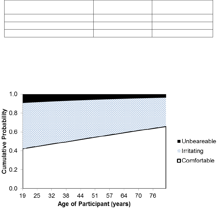
85
Table 48. Nighttime tests for simultaneous hypotheses on discomfort effect of pedestrian
location.
Hypothesis
Minimum Estimate
for Odds Ratio
Maximum Estimate
for Odds Ratio
(Pedestrian) ÷ (No pedestrian) = 1
0.81
2.16
(Either side) ÷ (Center) = 1
1.24
2.73
(Left side) ÷ (Right side) = 1
0.59
1.42
Age
Finally, this analysis found that driver age influenced the odds of higher discomfort after
controlling for other factors in the experimental design. This decreasing discomfort trend is
shown in figure 46 when no pedestrian was in the crosswalk and the LEDs were set at
2,200 candelas using the 2-5 flash pattern.
Figure 46. Graph. Estimated cumulative probabilities by age of participant for the discrete
scale of discomfort when using 2,200 candelas of intensity and the 2-5 flash pattern.
Key Findings Regarding Discomfort of Detection
For the analysis focusing on discomfort, results indicate the following:
• There were clear differences in discomfort between daytime and nighttime. It was
estimated that the odds of increasing discomfort were only influenced by LED intensity
during the day, whereas almost all experimental factors had an impact at night.
• LED intensity had a significant impact on discomfort levels during the nighttime only.
• The age of participants had an impact on discomfort levels during the nighttime only.
Discomfort tended to decrease with increasing participant age.
86
• Pedestrian position had an impact on discomfort level during the nighttime only. There
was no evidence for increasing discomfort levels when the pedestrian was present
compared to when the pedestrian was absent. However, locating the pedestrian at any
side of the crosswalk yielded higher discomfort compared to when the pedestrian was
located at the center of the crosswalk. This effect is probably associated with the
proximity to the active LEDs. No evidence of higher discomfort was found when the
pedestrian cutout was placed on the right side compared to when it was placed on
the left side.
• For nighttime only, there was convincing evidence of the flash pattern having an impact
on discomfort levels. Not surprisingly, this analysis found a significant increase of
discomfort associated with any flash pattern compared to no flash pattern at all.
• For nighttime only, LED location had a significant impact on discomfort levels. This
analysis found evidence of higher discomfort levels when the LEDs were located below
the sign compared to LEDs above the signs after controlling for other factors. Although
the trend is similar when comparing LEDs within the sign to LEDs above the sign, this
analysis did not find this difference statistically significant.
87
CHAPTER 4. DRIVER-YIELDING RESULTS FOR BEACONS PLACED ABOVE OR
BELOW CROSSING SIGN IN AN OPEN-ROAD SETTING
INTRODUCTION
For the open-road study, the test conditions were set to determine driver yielding when the
beacons were located above or below the warning sign. Both placements were studied at all
sites so that a similar driver population would see both treatments. This chapter describes the
methodology and results from the open-road study that investigated the effects of the placement
of yellow rapid-flashing beacons above or below the pedestrian crossing sign.
Due to the findings documented in this report, FHWA issued another interpretation: Official
Interpretation #4(09)-58 (I)—Placement of RRFBs Units Above Sign.
(3)
This permits the
placement of the beacons either above or below the crossing warning sign.
Study Overview
When IA-11 was issued in July 2008 for the RRFB, the only position of the beacons described in
the document was below the crossing warning sign and above the supplemental downward
diagonal arrow plaque.
(4)
As described in chapter 3 of this report, the position of the beacons had
an effect on drivers’ time to detect the presence and direction of crossing pedestrians as well as
discomfort glare during nighttime conditions on a closed course. Prior to developing the
proposed provisions for incorporating a rapid-flashing beacon traffic control device into the
MUTCD, it is important to determine which beacon position is most beneficial from a driver
yielding perspective.
(1)
This study sought to determine if mounting the beacons above the
pedestrian crossing sign was more effective in terms of driver yielding than the traditional
position below the sign.
Study Objective
The objective of this study discussed in this chapter was to determine benefits of different
positions for the RRFBs used with pedestrian crossing signs in an open-road setting. Because the
closed-course study presented in chapter 3 indicated that benefits may exist for placing the
beacons above the sign, the open-road study investigated if drivers yielded differently to RRFBs
placed above versus below the pedestrian crossing sign.
STUDY DEVELOPMENT
Study Sites
Near the conclusion of the closed-course study described in chapter 3, the researchers talked to
agency representatives and made requests during professional society meetings, seeking agencies
that would be willing to participate in the open-road research. Four agencies volunteered:
Aurora, IL; Douglas County, CO; Marshall, TX; and Phoenix, AZ. As a minimum, the agencies
were asked to identify at least two locations that either had existing RRFBs below the pedestrian
crossing sign that could be moved to the position above the sign or that would allow the beacons
to be installed in one position and then moved to the other position after the initial data

89
Table 49. Study site characteristics for above-below study.
Site
Posted
Speed
Limit
(mi/h)
Total
Crossing
Distance
(ft)
Crossing
Distance
to
Refuge
(ft)
ADT
Crosswalk
Marking
Pattern
Presence
of
Advanced
Stop or
Yield
Lines
Number of
Through
or Left-
Turn
Lanes
Crossed by
Pedestrians
Median
Type
Intersection
Geometry
a
Pedestrians
Crossing
per Hour
b
AZ-PH-04
35
61
20
23,700
Ladder
Yes
5
Raised
Midblock
with median
jog (50)
25
AZ-PH-05
35
49
NR
8,700
Ladder
Yes
3
TWLTL
Three legs
288
CO-DC-02
45 and
50
c,d
63
25
7,900
Ladder
No
4
Raised
Three legs
20
CO-DC-03
30
35
NR
2,600
Ladder
No
2
None
Four legs
15
CO-DC-04
30
35
NR
4,900
Ladder
No
2
None
Four legs
19
CO-DC-05
45
d
78
32
16,100
Ladder
Yes
4
Raised
Three legs
16
CO-DC-06
35 and
45
c
63
28
19,800
Ladder
Yes
4
Raised
Midblock (50)
36
CO-DC-07
45
d
78
34
18,800
Ladder
Yes
4
Raised
Midblock (50)
18
IL-AU-02
35
56
NR
30,800
Diagonal
No
4
TWLTL
Midblock (30)
17
IL-AU-03
35
30
NR
8,900
Diagonal
No
2
None
Midblock
(360)
19
IL-AU-04
35
94
50
9,400
Transverse
Yes
5
Raised
Four legs
18
TX-MA-01
30
40
NR
1,400
Diagonal
No
2
None
Midblock
(300)
137
TX-MA-02
30
30
NR
4,900
Diagonal
No
2
None
Three legs
17
Note: Sites are labeled as XX-YY-##, where XX represents the two-letter State code; YY represents the two-letter city code, and ## represents the site number within the city.
NR = No refuge; TWLTL = Two-way left-turn lane.
a
The distance (ft) to nearest intersection or major driveway is shown in parentheses (measured from the center of the crossing to the center of the nearest driveway/intersection).
b
This indicates the number of pedestrian crossings per hour during the daytime data collection period when the beacons were located below the crossing sign.
c
Speed limit varied by approach.
d
Site also includes the following two advance traffic control assemblies: pedestrian crossing (W11-2) warning sign with AHEAD (W16-9P) plaque, and SPEED LIMIT 25 (R2-1)
regulatory sign with WHEN FLASHING (S4-4P) plaque and a 12-inch circular beacon that is activated when the pedestrian pushes the pushbutton at the crossing.
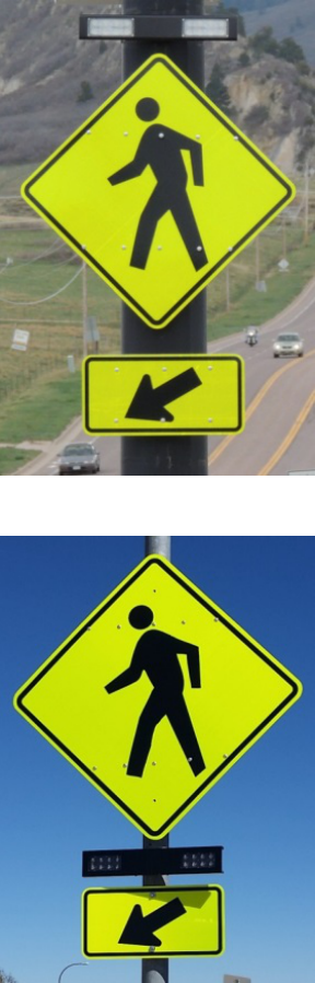
90
Study Assemblies
Examples of the study assemblies are shown in figure 47 and figure 48. The beacons were
mounted on a roadside pole to supplement either a W11-2 (pedestrian) or W11-15 (trail) crossing
warning sign with a diagonal downward arrow (W16-7p) plaque and located at or immediately
adjacent to a marked crosswalk. The flash pattern used at the study sites was the 2-5 flash
pattern. Table 50 provides information on installation order along with the dates of the data
collection.
Figure 47. Photo. Example of RRFB placed above the sign.
Figure 48. Photo. Example of RRFB placed below the sign.

91
Table 50. Installation and data collection dates.
Site
Existing
Beacons on
Assembly
Initial
Position
Date
Above
Installed
Date
Above
Data
Collection
Date
Below
Installed
Date
Below
Data
Collection
AZ-PH-04
RRFB
Below
2/20/2015
2/26/2015
Existing
2/17/2015
AZ-PH-05
RRFB
Below
2/20/2015
2/27/2015
Existing
2/16/2015
CO-DC-02
Activated
Above
3/18/2015
4/14/2015
4/27/2015
5/13/2015
CO-DC-03
Activated
Above
3/18/2015
4/14/2015
4/27/2015
5/14/2015
CO-DC-04
Activated
Above
3/18/2015
4/15/2015
4/27/2015
5/14/2015
CO-DC-05
Activated
Below
4/27/2015
5/14/2015
3/27/2015
4/13/2015
CO-DC-06
Activated
Below
4/27/2015
5/13/2015
3/27/2015
4/13/2015
CO-DC-07
Activated
Below
4/27/2015
5/13/2015
3/18/2015
4/14/2015
IL-AU-02
RRFB
Below
10/16/2014
10/28/2014
Existing
10/10/2014
IL-AU-03
RRFB
Below
10/16/2014
10/28/2014
Existing
10/10/2014
IL-AU-04
RRFB
Below
10/16/2014
10/29/2014
Existing
10/11/2014
TX-MA-01
RRFB
Below
3/25/2015
4/9/2015
Existing
2/12/2015
TX-MA-02
RRFB
Below
3/25/2015
4/10/2015
Existing
2/13/2015
Existing = RRFB was installed below the sign at site prior to the study.
Activated = Pedestrian-activated yellow circular 12-inch flashing beacons were activated.
Rotation
To account for the possibility that device installation order could affect the results, the RRFB
was installed above the sign first in some locations and second in other locations. For the
13 study sites, the RRFB was installed initially above the sign in 3 of the sites and was
previously installed or initially installed below the sign at the remaining sites.
DATA COLLECTION AND REDUCTION
Study Periods
The study was conducted between October 2014 and May 2015. Following installation of the
device in its initial position, the research team collected after data. Once the after data were
obtained, the research team requested that the device be installed in the second position
(i.e., RRFBs above the sign were moved below the sign and vice versa). After receiving
confirmation that the devices had been moved, the research team collected after data for the
second position.
Data were collected primarily during the daytime when vehicles were free-flowing. Because few
studies have collected data at night, the research team wanted to obtain some data for nighttime
conditions. The characteristics of the beacons and the site may have different impacts on driver
yielding during night conditions as compared to daytime conditions. Therefore, nighttime data
were collected for one site within each city.
92
Staged Pedestrian Protocol
The research team used a staged pedestrian protocol to collect driver yielding data to ensure that
oncoming drivers received a consistent presentation of approaching pedestrians. Under this
protocol, a member of the research team acted as a pedestrian using the crosswalk to stage the
conditions under which driver yielding would be observed. Each staged pedestrian wore similar
clothing (gray t-shirt, blue jeans, and gray tennis shoes) and followed specific instructions in
crossing the roadway. The staged pedestrian was accompanied by a second researcher, who
observed and recorded the yielding data on pre-printed datasheets.
Prior to the staged crossing maneuvers, researchers placed markers (either small contractor flags
or cones) at the edge of the traveled way at a distance corresponding to the AASHTO SSD value
for the posted speed limit at that site; one marker was placed in each direction approaching the
crosswalk.
(38)
SSD is 200 ft for 30 mi/h, 305 ft for 40 mi/h, and 360 ft for 45 mi/h. After the
study site had been prepared, the researchers followed the predetermined staged pedestrian
protocol, which was defined as follows:
1. The staged pedestrian approached the crosswalk as oncoming vehicles approached the SSD
marker activating the RRFB.
2. The staged pedestrian reached the edge of the crosswalk in time to place one foot in the
crosswalk (e.g., off the edge of the curb or curb ramp) within approximately 1 s of the
approaching driver(s) reaching the SSD marker.
3. The staged pedestrian waited to cross until approaching drivers yielded or until all
approaching drivers had traveled through the crosswalk.
4. The observer recorded how many motorists did/did not yield as well as how many were in a
position to yield for each crossing maneuver. Drivers were considered to be in position to
yield if they were upstream of the SSD marker when the staged pedestrian was positioned at
the edge of the crosswalk. Each such vehicle that did not yield was counted as was each
yielding vehicle. Of the vehicles in a position to yield, a vehicle was considered to be
yielding if the driver slowed or stopped for the purpose of allowing the waiting pedestrian to
cross. Any vehicles traveling in a platoon behind yielding vehicles were not counted because
those drivers did not have the opportunity to make a decision on whether to yield to the
pedestrian; therefore, the maximum number of yielding vehicles possible for each crossing
maneuver was equal to the number of travel lanes through which the crosswalk passed.
5. Yielding was observed separately for each direction of vehicular travel because Arizona,
Colorado, Illinois, and Texas law is written such that drivers must yield to pedestrians in or
approaching their half of the roadway.
6. The observer noted any unusual events or noteworthy comments for each crossing.
7. Once the crosswalk was clear (i.e., the approaching vehicle had either stopped or passed
through the crossing), the staged pedestrian crossed the street and waited on the sidewalk or
roadside until all vehicles visible during that crossing traveled through the crosswalk. After

93
all such vehicles had left the study site, the staged pedestrian prepared for the next crossing
maneuver.
The protocol called for the completion of a minimum of 20 staged crossing maneuvers in each
direction of travel for a total of 40 crossings. Observation periods were chosen such that vehicle
traffic was heavy enough to create frequent yielding situations but not heavy enough for
congestion to affect speeds. Data were always collected during daylight and in good weather,
avoiding rain, wet pavement, dusk or dawn, or other conditions that could affect a driver’s ability
to see and react to a waiting staged pedestrian.
A minimum of 40 (and a desired 60) staged pedestrian crossings were collected at each site
within each time period during daytime. Because of the length of time needed to collect the
crossing, a minimum of 40 staged pedestrians were collected at night.
Driver Yielding
After completing the data collection, researchers entered the crossing data and the site
characteristics data from the field worksheets into an electronic database. The average yielding
rate for a site was calculated, as shown in figure 49; however, data for individual crossings were
used in the statistical evaluation.
Figure 49. Equation. Driver yielding rate.
Table 51 lists the driver yielding rates for each site and beacon position along with the number
of staged pedestrian crossings for the nighttime data collection periods. Driver yielding to
staged pedestrians at night averaged 68 percent for the above position and 65 percent for the
below position.
Table 51. Nighttime driver yielding rate by site and beacons position.
Site
Number of
Staged
Crossings for
Above Position
Driver Yielding
for Above
Position
(Percent)
Number of
Staged
Crossings for
Below Position
Driver Yielding
for Below
Position
(Percent)
AZ-PH-05
44
81
60
85
CO-DC-06
41
80
40
73
IL-AU-03
60
50
62
46
TX-MA-01
60
73
39
74
Total
205
68
201
65
Table 52 shows similar results for the daytime data collection periods. During the daytime, driver
yielding to staged pedestrians averaged 64 percent for the above position and 61 percent for the
below position. For several sites, neither beacon position showed a large increase in driver
yielding as compared to the other. The range of driver yielding to staged pedestrians at these
sites ranged from 19 to 98 percent.
Yielding rate =
Number of yielding vehicles
Number of yielding vehicles + Number of non ̵ yielding vehicles

94
Table 52. Daytime driver yielding rate by site and beacon position.
Site
Number of
Staged
Crossings for
Above Position
Driver Yielding
for Above
Position
(Percent)
Number of
Staged
Crossings for
Below Position
Driver Yielding
for Below
Position
(Percent)
AZ-PH-04
60
47
60
54
AZ-PH-05
60
88
43
94
CO-DC-02
61
93
58
98
CO-DC-03
60
82
41
66
CO-DC-04
58
90
60
86
CO-DC-05
60
92
60
79
CO-DC-06
60
82
56
93
CO-DC-07
60
89
60
87
IL-AU-02
59
20
58
19
IL-AU-03
61
42
64
59
IL-AU-04
60
67
60
32
TX-MA-01
42
93
63
87
TX-MA-02
61
85
62
77
Total
762
64
745
61
RESULTS
When a driver approaches a pedestrian crossing, the driver either yields and stops (or slows) the
vehicle or does not yield to the waiting pedestrian. This binary behavior (yield or no yield) can
be modeled using logistic regression. A significant advantage of using logistic regression is it
permits consideration of individual crossing data rather than reducing all the data at a site to only
one value. For the dataset available within this study, that means that over 1,900 data points
could be available (i.e., all the unique staged crossings recorded) rather than only 34 data points
(i.e., the number of study sites by number of assemblies and by day or night). For the analyses
that focused on comparing the below position to the above position, that means 1,507 data points
rather than 26 data points were available. These larger sample sizes could result in finding
significant relationships that would not be apparent with a smaller dataset. Additionally, it is
possible to utilize random effects to account for site-specific differences since such differences
induce a correlation structure in the dataset.
Using logistic regression to model the relationships assumes that the logit transformation of
the outcome variable (i.e., yielding rate) has a linear relationship with the predictor variables,
which results in challenges in interpreting the regression coefficients. The interpretation of such
coefficients is not on the yield rate changes directly but a change in the odds of motorists
yielding (odds are defined as the ratio of the number of yielding motorists to the number of non-
yielding motorists). The regression coefficients can be transformed and interpreted as odds ratios
of different levels of the corresponding independent variable. In other words, a unit change of the
independent variable corresponds to a change in the odds of motorists yielding, which is an
alternative way to express a change in yielding rate. More details on these types of models can be
found in the literature.
(47)
All the statistical analyses were performed using R, an open-source
statistical language and environment, and two open-source packages for fitting GLMMs.
(48,44,45)
95
COMPARISON OF BELOW TO ABOVE
Because a previous study that included RRFBs found posted speed limit, crossing distance, and
city influenced driver yielding, the initial analyses were also conducted with those variables.
(35)
In addition, a variable to reflect the intersection configuration was included, as preliminary
reviews indicated that the number of approach legs may be related to yielding results.
Preliminary modeling revealed a correlation between road type (e.g., number of lanes and
median treatment) and speed limit present in the dataset; therefore, only posted speed limit was
included in the final model. Models were examined that included other variables, such as total
crossing distance; however, the best results were found when the variables shown in table 53
were included. The reference level for a driver yielding in the model was estimated for the
following conditions: an above sign during the daytime in Arizona with a three-leg intersection.
From the preliminary review of the results in table 52, it appears that there were only minor, if
any, differences between the above and below position for the RRFBs. The results from the
GLMM are shown in table 53, and these results support that observation. The results indicate
that there were no significant differences between the two beacon locations (p-value = 0.1611).
The day/night variable was significant (p-value = 0.0005), which indicates that there were day/
night differences for this dataset regarding driver yielding. It appears that Illinois had notably
lower driver yielding as compared to the base State, Arizona. An adjusted p-value for multiple
comparisons is required to make a formal assessment. Texas and Colorado were not different
from Arizona. The model also indicates that the driver yielding at the midblock offset
configuration was statistically different from the driver yielding at the three-legged intersections.
A caution with this finding is offered since there was only one site with a midblock offset
configuration in the dataset.

96
Table 53. GLMM results comparing below to above.
Variable
Estimate
Standard
Error
t-value
p-value
Significance
c
Reference
a
0.10770
1.04333
0.103
0.917783
Below
-0.09931
0.07087
-1.401
0.161107
Night
-0.41899
0.12048
-3.478
0.000506
***
Posted speed limit
0.05858
0.02718
2.155
0.031185
*
State
Colorado
-0.26452
0.56242
-0.470
0.638119
b
Illinois
-2.18731
0.64555
-3.388
0.000703
b
***
Texas
0.02124
0.60734
0.035
0.972104
b
Intersection
configuration
Four legs
-0.07459
0.47508
-0.157
0.875249
b
Midblock
-0.49582
0.44650
-1.110
0.266803
b
Offset midblock
-2.11671
0.57363
-3.690
0.000224
b
***
Estimate = Natural logarithm of the ratio = Odds (coefficient level)/Odds (reference level). In the case of reference level,
estimate is the log-odds of the average yielding rate at the reference level.
t-value = Conservative estimate of the z-value, which is the standard normal score for the estimate, given the hypothesis
that the actual odds ratio equals 1.
p-value: Probability that the observed log-odds ratio is at least as extreme as the estimate, given the hypothesis that the
actual odds ratio equals 1.
a
Reference level driver yielding in the model is estimated for the following conditions: above, day, Arizona, and
three-legged intersection.
b
These p-values require an adjustment for multiple comparisons if inferences about different yielding rates among States or
among configuration are intended.
c
Significance values are as follows: blank cell = p > 0.10; ~ = p < 0.10; * = p < 0.05; ** = p < 0.01; and *** = p < 0.001.
97
CHAPTER 5. DRIVER-YIELDING RESULTS FOR THREE RRFB PATTERNS IN AN
OPEN-ROAD SETTING
INTRODUCTION
This chapter describes the methodology and results from an open-road study that examined
different flash patterns for use with yellow RRFBs.
Study Overview
When IA-11 was issued in July 2008 for the RRFBs, the only flash pattern that had been tested
was the 2-5 flash pattern.
(4)
Because the 2-5 flash pattern appears be a 2-3 flash pattern according
to the human eye, several devices were installed with the 2-3 flash pattern rather than the
2-5 flash pattern. Only after looking at the flash pattern using an oscilloscope were transportation
professionals able to determine that the original devices had a 2-5 flash pattern, which is why
FHWA changed the flash pattern from a 2-3 flash pattern to a 2-5 flash pattern in Official
Interpretation 4(09)-21.
(9)
An inability to accurately determine the number of pulses within the 2-5 RRFB flash pattern was
later confirmed in the closed-course study (see chapter 3). The same study found that certain
flash patterns (i.e., those that could be characterized as having limited or no dark periods within
the flash pattern) negatively influenced the amount of time participants needed to identify a
pedestrian’s direction of travel. Prior to developing the proposed provisions for incorporating the
RRFB a rapid-flashing beacon traffic control device into the MUTCD, it is important to
determine which flash patterns are acceptable from the perspectives of effectiveness and
simplicity.
(1)
This study sought to determine if less complicated flash patterns and flash pattern
with different proportions of dark and light periods could be as or more effective than the
2-5 flash pattern.
Study Objective
The objective of this study was to determine if the use of simpler flash patterns or flash patterns
with a greater proportion of dark periods resulted in different driver yielding rates at uncontrolled
crosswalks in an open-road setting. This study’s measure of effectiveness (MOE) was the
number of drivers who did and did not yield at crosswalks during staged pedestrian crossings.
STUDY DEVELOPMENT
Study Sites
The cities of College Station, TX, and Garland, TX, along with TAMU agreed to participate in
the study by providing locations where the research team could install temporary equipment.
Table 54 lists the sites included in the study. A goal was to try to match the distribution of site
characteristics used in the original FHWA study on RRFBs.
(16)
For example, the research team
preferred locations on multilane roads so that yielding behavior associated with the multiple
threats issue could be observed. Because of limited ability to mount temporary beacons on

98
overhead mast arms, the research team did not consider locations where the RRFB had been
installed on mast arms over the roadway.
Table 54. List of sites for rapid flash pattern study.
Site ID
Posted Speed
Limit (mi/h)
Number of
Lanes
Median
Crossing
Distance (ft)
CS-02
40
4
Flush
56
CS-03
30
2
Flush
37
GA-02
40
4
Flush
58
GA-06
40
4
Raised
80
GA-07
45
4
Raised
82
GA-10
40
4
Raised
62
GA-11
40
4
Raised
62
GA-13
40
4
Raised
55
Temporary Light Bar
To conduct an in-field evaluation of multiple flash patterns, the research team needed to be able
to set the flash pattern and brightness of the beacons at the study sites in a quick, reliable, and
consistent manner. Because of the difficulties with working with different equipment in different
cities and unknown characteristics for the beacons at these locations (such as brightness), the
research team designed temporary controllers to be used with temporary light bars. In the field,
the temporary light bars were mounted in front of existing RRFB light bars.
The temporary light bar setup was designed such that it was not obvious that the beacons being
observed during the staged pedestrian crossings were any different from the permanent RRFB
equipment. Figure 50 shows an example of TTI personnel installing the temporary light bar at a
site, and figure 51 shows an example of the installed light bar being used by a staged pedestrian.
The staged pedestrian had a remote control to activate the light bars and activated the device if a
non-staged pedestrian approached the crossing while the temporary light bars were installed.
Figure 50. Photo. Installation of the light bar in field.
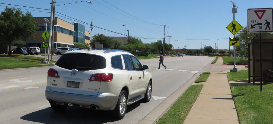
99
Figure 51. Photo. CS-02 study site with installed temporary light bars and staged
pedestrian crossing.
Flash Patterns
The study budget and parameters made it possible to test four different conditions at each study
site. One of the four conditions was reserved for collecting driver yielding data with the existing
equipment. Data were collected with the existing equipment in order to control for differences
between the existing equipment and the temporary equipment. The other three conditions used
the temporary equipment. Of the three remaining conditions, one condition was reserved for the
2-5 flash pattern.
To determine flash patterns for the other two conditions, a flash pattern workshop was held at
TTI. The workshop included a selection of licensed transportation engineering professionals,
representatives of FHWA, and TTI research staff. The patterns were initially reviewed using a
mockup of a rectangular beacon light bar and a controller in a conference room. Several pre-
developed patterns were shown to the participants. Based on participant comments, new patterns
were developed. For example, some flash patterns were changed to have more dark periods or to
have periods where both beacons were on. A reason for wanting increased dark periods for some
of the flash patterns for this study was a preliminary finding from a closed-course research study
(see chapter 3) that indicated drivers could determine the direction a pedestrian was walking in a
crosswalk more quickly when the flashing traffic control devices had larger dark periods.
After identifying a short list of potential patterns during the meeting in the conference room,
the meeting moved to a TTI closed-course location to look at the potential patterns in the field
during the nighttime setting. The participants parked the vehicle 200 ft from a crosswalk on a
two-lane approach with RRFB assemblies located on both sides of the roadway. The patterns
developed during the conference room meeting were demonstrated to the meeting participants in
the field. Based on the meeting participants’ comments, two potential patterns were selected.
These two patterns were demonstrated to FHWA representatives, and final approval was given to
use these two flash patterns as the two remaining conditions for the open-road study.
100
Figure 52 illustrates the three patterns selected for testing in the field using the temporary light
bars. The patterns considered in this study included the following:
• Temporary light bar and pattern using a combination of long and short flashes
(i.e., blocks).
• Temporary light bar and a pattern using a combination of wig-wag and
simultaneous flashes.
• Temporary light bar and the 2-5 flash pattern.
• Existing equipment and the 2-5 flash pattern or 2-3 pattern (whichever was present at the
site). Because of when the cities installed the existing RRFBs, some of the sites may have
had the 2-3 flash pattern rather than the 2-5 flash pattern with the existing equipment.
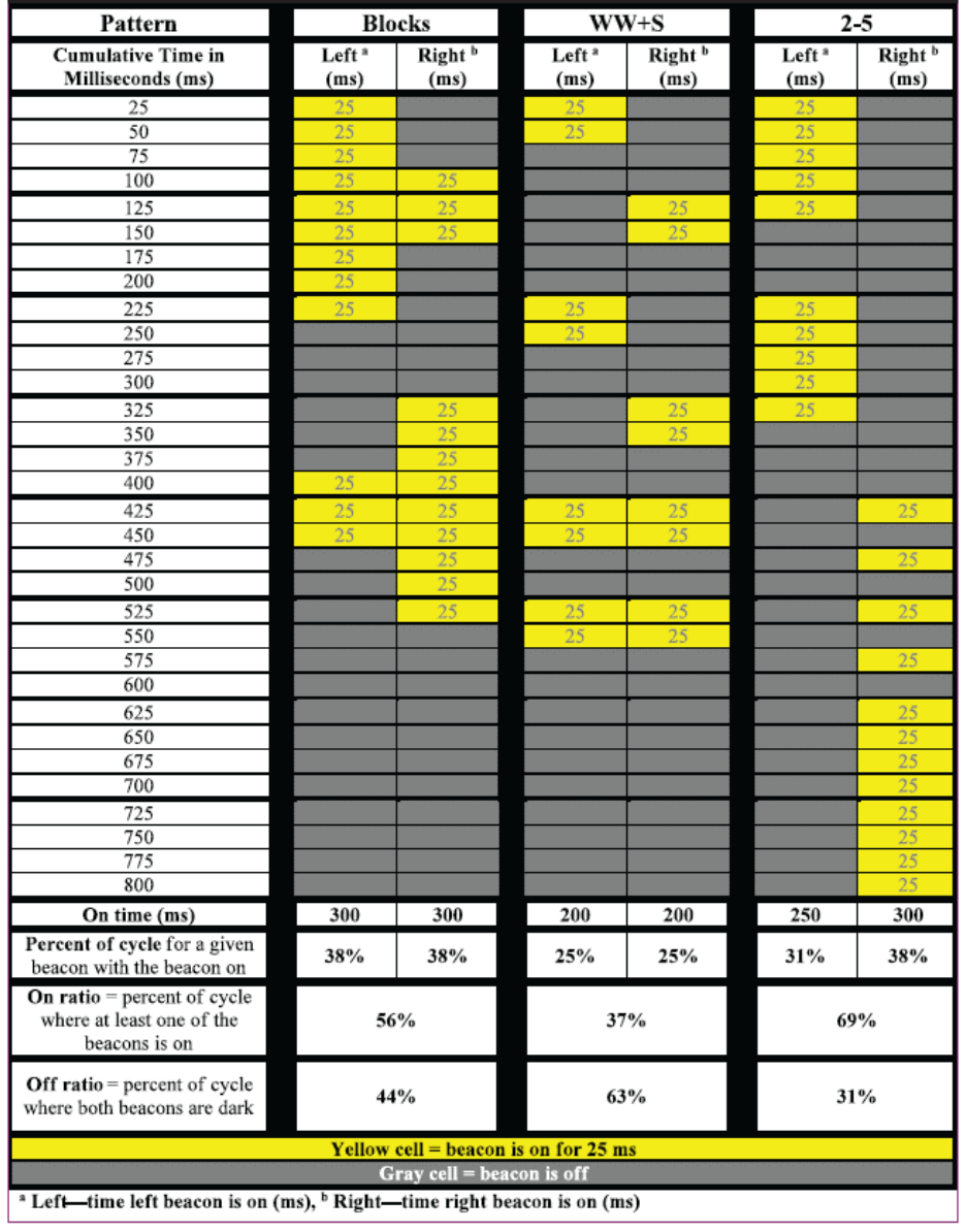
101
Figure 52. Illustration. Flash patterns studied.
(49)

102
Brightness of LEDs
Preliminary findings from the closed-course study (see chapter 3) indicate that brightness of the
beacons can influence how quickly a participant can detect a pedestrian within a crosswalk.
Therefore, the same brightness level was used for the three flash patterns tested with the
temporary light bars. Table 55 shows the target and measured intensity for the beacons when
measured at horizontal and vertical angles of 0 degrees. The table also shows the measured
optical power along with the on and off ratios (i.e., percent of the cycle where at least one of the
beacons was on or where both beacons were dark, respectively).
Table 55. Brightness measurements.
Flash Pattern with
Temporary
Equipment
Target
Intensity
(Candela)
Measured
Target
Intensity
(Candela)
Optical Power
(Candela-s/min)
On Ratio
(Percent)
Off Ratio
(Percent)
2-5
1,400
1,414
58,300
69
31
Blocks
1,400
1,415
63,700
56
44
Wig-wag and
simultaneous (WW+S)
1,400
1,418
42,500
37
63
Sample Size
Based on a statistical analysis of past driver yielding data at RRFB locations in Texas, the
research team estimated it would take between 7 and 13 sites to obtain a sufficient sample of
data to permit detection of at least a 5 percent difference in driver yielding.
(36)
With available
resources for the study, a total of eight sites were selected for testing. Based on previous
experience, the minimum number of staged pedestrian crossings for each condition was set at 40.
Flash Pattern Order
The order that treatments were presented could have had an effect on results; therefore, flash
pattern order for the sites was randomized. Table 56 lists the order that the flash patterns were
installed at each site.

103
Table 56. Flash pattern order by test site location.
Site ID
Initial Flash Pattern
Second Flash Pattern
Third Flash Pattern
Fourth Flash Pattern
GA-02
Temporary; 2-5
Existing; 2-5 or 2-3
Temporary; blocks
Temporary; WW+S
CS-02
Existing; 2-5 or 2-3
Temporary; blocks
Temporary; WW+S
Temporary; 2-5
CS-03
Temporary; blocks
Temporary; WW+S
Temporary; 2-5
Existing; 2-5 or 2-3
GA-06
Temporary; WW+S
Temporary; 2-5
Existing; 2-5 or 2-3
Temporary; blocks
GA-07
Temporary; 2-5 flash
Existing; 2-5 or 2-3
Temporary; blocks
Temporary; WW+S
GA-10
Existing; 2-5 or 2-3
Temporary; blocks
Temporary; WW+S
Temporary; 2-5
GA-11
Temporary; blocks
Temporary; WW+S
Temporary; 2-5
Existing; 2-5 or 2-3
GA-13
Temporary; WW+S
Temporary; 2-5
Existing; 2-5 or 2-3
Temporary; blocks
Note: Flash patterns are defined as follows: 2-5 = 2-5 flash pattern and 2-3 = 2-3 flash pattern.
DATA COLLECTION AND REDUCTION
Study Periods
The data were collected during daytime conditions in February and March 2014. The research
team avoided Monday mornings and Friday afternoons along with weekends because travel
patterns for those time periods can be different from travel patterns associated with a
typical weekday.
Staged Pedestrian Protocol
The research team used a staged pedestrian protocol to collect driver yielding data to ensure that
oncoming drivers received a consistent presentation of approaching pedestrians. Under this
protocol, a member of the research team acted as a pedestrian using the crosswalk to stage the
conditions under which driver yielding would be observed. Each staged pedestrian wore similar
clothing (gray t-shirt, blue jeans, and gray tennis shoes) and followed specific instructions in
crossing the roadway. The staged pedestrian was accompanied by a second researcher, who
observed and recorded the yielding data on pre-printed datasheets. Additional information on the
staged pedestrian protocol followed is available in chapter 4 of this report or in “Driver Yielding
to Traffic Control Signals, Pedestrian Hybrid Beacons, and Rectangular Rapid-Flashing Beacons
in Texas.”
(36)
DATA REDUCTION
After completing the data collection, researchers entered the crossing data and the site
characteristics data from the field worksheets into an electronic database. The average yielding
rate for a site was calculated; however, data for individual crossings were used in the statistical
evaluation. Table 57 lists the driver yielding rates for each site, type of light bar, and flash
pattern. As shown in the final row of the table, the three flash patterns used with the temporary
light bar had similar average driver yielding rates—between 78 and 80 percent. When comparing
the results for the individual sites, some sites did have larger differences between the different
flash patterns.

104
Table 57. Driver yielding rate by site and pattern.
Site
Temporary Light
Bars with WW+S
(Percent)
Temporary
Light Bars with
Blocks (Percent)
Temporary Light
Bars with
2-5 Flash Pattern
(Percent)
Existing Light
Bars with 2-5 or
2-3 Flash Patterns
(Percent)
CS-02
63
50
61
44
CS-03
84
94
87
76
GA-02
76
75
67
98
GA-06
96
81
85
96
GA-07
78
92
84
92
GA-10
90
94
89
94
GA-11
87
90
82
92
GA-13
80
84
84
95
Total
80
80
78
81
RESULTS
When a driver approaches a crossing, the driver either yields and stops the vehicle or does not
yield to the waiting staged pedestrian. This binary behavior (yield or no yield) can be modeled
using logistic regression. A significant advantage of using logistic regression is it permits
consideration of individual crossing data rather than reducing all the data at a site to only
one value. For the dataset available within this study, that means over 1,100 data points could
be available (i.e., all the unique staged crossings recorded) rather than only 32 data points (i.e.,
the number of study sites by number of flash patterns). The larger sample size provides more
detailed data and could result in finding significant relationships that would not be apparent with
a smaller dataset.
Using logistic regression to model the relationships assumes that the logit transformation of the
outcome variable (i.e., yielding rate) has a linear relationship with the predictor variables, which
results in challenges in interpreting the regression coefficients. Odds ratios can be used to
illustrate how to interpret the logistic regression results. The interpretation of such coefficients is
not on the yield rate changes directly but a change in the odds of motorists yielding (odds are
defined as the ratio of the number of yielding motorists to the number of non-yielding motorists).
The regression coefficients can be transformed and interpreted as odds ratios of different levels
of the corresponding independent variable. In other words, the odds ratio is the expected change
in the odds of motorists yielding per unit change of the independent variable. More details on
these types of models can be found in the literature.
(47)
All the statistical analyses were
performed using R, an open-source statistical language, and environment and two open-source
packages for fitting GLMMs.
(48,45)
Patterns Used with Temporary Light Bars
From the preliminary review of the results in table 57, it appears that there were only minor, if
any, differences between the tested flash patterns. The results from the GLMM are shown in
table 58. Statistical significance of coefficients was obtained from comparing the coefficient
(i.e., parameter estimate) to a value of zero. If an estimate is found to be statistically different
from zero, then the variable has a statistically significant effect on the odds of driver yielding.

105
Additionally, if the coefficient is different from zero, then the odds ratio is different from 1.
Conversely, coefficients without statistical significance indicate an odds ratio indistinguishable
from one, thus indicating that the variable has no bearing on driver yielding rate. In this study,
the reference level for a driver yielding in the model was estimated as follows: temporary light
bar with a 2-5 flash pattern in College Station, TX.
Table 58. Linear mixed-effects model results for flash patterns used with temporary light
bars.
Variable
Estimate
Standard Error
DF
t-value
p-value
Reference
a
1.3864637
0.9582977
941
1.4467986
0.1483
Temporary; blocks
0.1662325
0.1503383
941
1.1057233
0.2691
Temporary; WW+S
0.1164097
0.1452238
941
0.8015884
0.4230
Garland, TX
0.8213472
0.5663119
5
1.4503443
0.2067
Crossing distance (ft)
-0.0090980
0.0184713
5
-0.4925464
0.6432
Estimate = Natural logarithm of the ratio = odds (coefficient level)/odds (reference level). In the case of reference
level, estimate is the log-odds of the average yielding rate at the reference level.
t-value = Conservative estimate of the z-value, which is the standard normal score for the estimate, given the
hypothesis that the actual odds ratio equals 1.
p-value = Probability that the observed log-odds ratio is at least as extreme as the estimate, given the hypothesis
that the actual odds ratio equals 1.
a
Reference level driver yielding in the model is estimated for the following conditions: 2-5 flash pattern used with
temporary light bars in College Station, TX.
Because a previous study on RRFBs found that posted speed limit, crossing distance, and city
influenced driver yielding, the analysis considered those variables initially. However, for this set
of sites, posted speed limit and crossing distance were correlated; therefore, posted speed limit
was removed. Site selection was heavily influenced by whether four lanes were present and
whether the beacons were located on the roadside rather than overhead. In other words, site
selection was not a function of the posted speed limit and crossing distance, and a high number
of sites had one posted speed limit (40 mi/h for six of the eight sites), which did not provide a
sufficient range for parameter estimation on that variable. The city (Garland, TX, or College
Station, TX) was included as a fixed effect, with the results shown in table 59. Both city and
crossing distance were found to be not significant for this dataset.
The p-values from table 58 were adjusted to allow multiple comparisons, as shown in table 59.
The table indicates that there were no significant differences between the 2-5 flash pattern and
the WW+S flash pattern (p-value = 0.707), between the 2-5 flash pattern and the blocks flash
pattern (p-value = 0.517), between the blocks flash pattern and WW+S flash pattern (p-value =
0.941), or between blocks, WW+S, or the 2-5 flash pattern (p-value = 0.516).

106
Table 59. Simultaneous comparisons on flash pattern differences.
Hypothesis
Estimate
Standard
Error
z-value
Pr( >|z|)
a
Temporary; blocks − Temporary 2-5 flash pattern = 0
0.16623
0.14994
1.109
0.517
Temporary; WW+S − Temporary; 2-5 flash
pattern = 0
0.11641
0.14484
0.804
0.707
Temporary; blocks − Temporary; WW+S = 0
0.04982
0.14872
0.335
0.941
(Temporary; blocks and Temporary; WW+S) −
(Temporary; 2-5 flash pattern) = 0
0.14132
0.12728
1.11
0.516
a
Adjusted p-values were reported using a single-step method.
2-5 Flash Pattern
The previous evaluation kept the temporary light bar constant, while this evaluation kept the
2-5 flash pattern constant. Comparing the results between the 2-5 flash pattern used with the
temporary light bars and the results when the 2-5 flash pattern was used with the existing
equipment indicates that a difference may exist. As shown in table 57, the average yielding for
the 2-5 flash pattern with temporary light bars was 78 percent, while the average yielding for the
existing equipment was slightly higher at 81 percent. Overall, the driver yielding rates were
higher for the existing light bars for the Garland, TX, sites, and the driver yielding rates were
lower for the existing light bars for the College Station, TX, sites.
Table 60 shows the results for the LMM, which found that the equipment (p-value = 0.0010) and
the city (p-value = 0.0205) were both significant. Because these statistical significant differences
existed, they indicate that characteristics of the city, the roadway, and the beacons other than
flash pattern had an effect on driver yielding. Even with accounting for crossing distance and
city, a statistical significant difference was found between the existing and temporary light bars.
Therefore, other characteristics that were not measured (i.e., brightness) are possibly influencing
a driver’s decision to yield or not yield. The reference level driver yielding in the model was
estimated as having existing light bars in College Station, TX.
Table 60. LMM results comparing the 2-5 flash pattern with temporary and existing
equipment.
Variable
Estimate
Standard Error
DF
t-value
p-value
Reference
a
1.4748929
0.8625094
644
1.71002
0.0877
Temporary beacons
-0.5002792
0.1516542
644
-3.298814
0.0010
Garland, TX
1.6766262
0.5014311
5
3.343682
0.0205
Crossing distance (ft)
-0.0131371
0.0166508
5
-0.788978
0.4659
Estimate = Natural logarithm of the ratio = odds (coefficient level)/odds (reference level). In the case of reference
level, estimate is the log-odds of the average yielding rate at the reference level.
t-value = Conservative estimate of the z-value, which is the standard normal score for the estimate, given the
hypothesis that the actual odds ratio equals 1.
p-value = Probability that the observed log-odds ratio is at least as extreme as the estimate, given the hypothesis
that the actual odds ratio equals 1.
a
Reference level driver yielding in the model is estimated for the following conditions: existing light bars in
College Station, TX.
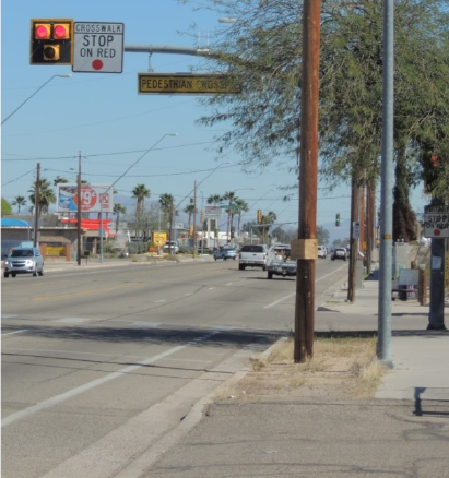
107
CHAPTER 6. PHB STUDY
INTRODUCTION
This chapter describes the methodology and results from a study that examined driver and
pedestrian behavior at PHBs. The PHB, or HAWK as it is known in Tucson, AZ, is a traffic
control device used at pedestrian crossings. The crossing typically has the crosswalk across only
one of the major road approaches. The PHB’s vehicular display faces are typically located on
mast arms over the major approaches to an intersection and in some locations on the roadside.
An example is shown in figure 53 for an installation in Tucson, AZ, and in figure 54 for an
installation in Austin, TX. The face of the PHB consists of two red indications above a single
yellow indication. It rests in a dark mode, but when activated by a pedestrian, it first displays a
few seconds of flashing yellow followed by a steady yellow change interval and then displays a
steady red indication to drivers, which creates a gap for pedestrians to cross the major roadway.
During the flashing pedestrian clearance interval, the PHB displays an alternating flashing red
indication to allow drivers to proceed after stopping if the pedestrians have cleared their half of
the roadway, thereby reducing vehicle delays.
Figure 53. Photo. Example of PHB installation in Tucson, AZ.
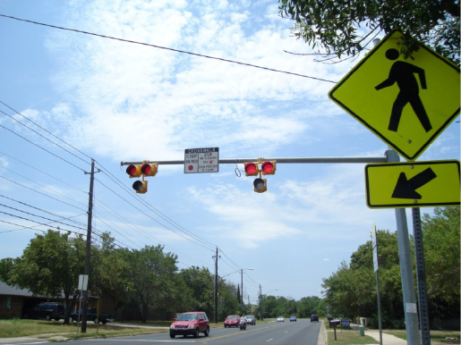
108
Figure 54. Photo. Example of PHBs being used in Austin, TX.
The PHB has shown great potential for improving pedestrian safety; however, questions remain
regarding under what roadway conditions—such as crossing distance (i.e., number of lanes) and
posted speed limit—should it be considered for use.
(26,27)
In addition, there are questions about
the device’s operations. For example, a current topic of discussion within the profession is the
way drivers treat a PHB when it is dark. PHBs dwell in a dark mode for drivers until activated
by a pedestrian. A concern among some is that drivers will see a dark PHB and treat it as a
Stop sign, similar to the required behavior for a dark traffic signal that has experienced a
power outage.
The STC of the NCUTCD assists in developing language for chapter 4 of the MUTCD.
(1)
It is
interested in research and/or assistance in refining material on the PHB. The PHB was first
included in the 2009 MUTCD, which discusses the design and operations of the device along
with guidance for installation categorized by low speed (roadways where speeds are 35 mi/h or
less) and high speed (roadways where speeds are more than 35 mi/h).
(1)
The 2009 MUTCD also
indicates that the PHB “…should be installed at least 100 ft from side streets or driveways that
are controlled by Stop or Yield signs”
(1)
(pg. 449) In 2011, the STC recommended to remove
that statement because it was a significant change from what was reviewed and approved by
the National Committee in 2007 and what was proposed in the Notice of Proposed Amendment
(NPA) for the 2009 MUTCD.
(50)
The statement was added to the PHB 2009 MUTCD discussion
just prior to publication. The STC provided the following concerns with the 100-ft distance (with
additional details added by this study’s research team based on reviewer comments):
• The result of the added 100-ft guidance, if followed, is that these beacons could not be
used at unsignalized intersections or driveways. The NPA language did not include any
limitations (either standard or guidance) on the locations for use of the PHB; therefore,
the 100-ft change was not subject to public review and comment.
• The 100-ft offset listed in the guidance is not supported by research or experimentation
with this device. Most sites used for experimentation when the PHB was being tested
were intersection or driveway locations which were the natural crossing locations.
109
Therefore, the typical use of the device as tested, which ultimately proved to be
successful, is recommended against in the 2009 MUTCD.
• All of the sites included in the FHWA study that evaluated the safety effectiveness of
these devices were at stop-controlled intersections or major driveways.
(27)
The study was
performed just prior to the publication of the 2009 MUTCD.
• The 100-ft guidance, if followed, causes increased mobility difficulties and discomfort
for pedestrians with disabilities and forces all pedestrians to experience increased
inconvenience if they must divert away from their desired crossing location at an
intersection or driveway to a different crossing point located 100 ft or more away which
would likely lead to 200 ft or more out-of-way travel. If the PHB is not placed at the
natural crossing locations, it is likely it will not be used by most pedestrians, and their
value as a safety device could be compromised.
Because of the questions being asked regarding driver and pedestrian behaviors with PHBs,
FHWA sponsored a study to record behaviors at existing sites.
Study Objective
The objective of this study was to determine actual driver and pedestrian behaviors at locations
with a PHB.
STUDY SITES
Through existing contacts and research team knowledge along with responses to requests, the
research team compiled a preliminary list of PHB locations. Data for key variables (posted speed
limit, number of through lanes, and the type of median treatment) were gathered and added to the
list for the PHBs in communities with multiple installations. Pedestrian crossings on higher
speed roadways and with wider crossings have historically experienced lower driver yielding, so
posted speed limit and crossing distance (as reflected by number of lanes) were selected as key
variables. The goal was to have at least eight sites with higher posted speed limits (defined for
this study as being 40 mi/h or higher) and four sites with lower posted speed limits (defined for
this study as being 35 mi/h or lower). The presence of a median can provide refuge for a
crossing, which may affect the measures of effectiveness considered for this study, so it was also
included in the original study matrix. Because of efficiencies in data collection, data were
collected for a total of 20 sites. Roadway and traffic characteristics for the sites are listed in
table 61.

110
Table 61. Site characteristics.
Site
Name
a
Roadway
Configuration
Number
of
Approach
Legs
Posted
Speed
Limit
(mi/h)
ADT
Pedsetrians/
Hour
b
Number
of
Through
Lanes
Park
Lane/
Bike Lane
Width (ft)
Median
Type
Median
Width
(ft)
Total
Crossing
Distance
(ft)
TU-003
Intersection
4
35
7,400
4.8
4
NA/6
TWLTL
13
69
TU-004
Intersection
3
40
7,600
9.3
4
NA/6
TWLTL
13
82
TU-007
Intersection
3
40
8,700
8.9
4
NA/6
TWLTL
13
69
TU-021
Intersection
4
40
31,000
8.2
4
NA/5
TWLTL
12
83
TU-037
Intersection
4
35
27,500
11.1
4
NA/5
TWLTL
11
75
TU-042
Intersection
4
30
5,100
14.2
4
NA/NA
Raised
8
88
TU-059
Intersection
4
40
28,400
3.1
4
NA/4
Raised
8
89
TU-070
Intersection
3
40
29,900
3.6
4
NA/4
Raised
7
80
TU-072
c
Intersection
4
40
41,300
7.6
6
NA/6
Raised
10
119
TU-073
Intersection
4
40
13,800
13.3
6
NA/6
Raised
8
93
TU-090
Intersection
4
40
10,100
1.1
4
NA/7
Raised
8
92
TU-091
Intersection
3
35
5,200
2.5
4
13/5
Raised
11
112
AU-04
Intersection
4
35
26,600
11.5
4
NA/NA
Raised
10
50
AU-07
c
Midblock (50)
d
2
35
24,600
23.3
4
NA/NA
Raised
8
57
AU-11
Intersection
3
40
26,900
6.4
4
8/NA
TWLTL
12
90
AU-16
Intersection
4
35
28,500
18.5
4
NA/NA
TWLTL
12
60
AU-21
Midblock (60)
d
2
35
27,100
20.0
4
NA/NA
None
NA
40
AU-22
Midblock (70)
d
2
45
19,600
38.3
4
NA/6
TWLTL
12
68
AU-24
Intersection
4
35
14,100
20.7
4
NA/NA
Raised
6
68
AU-27
Midblock (80)
d
2
35
21,200
10.7
4
NA/6
Raised
6
80
NA = Not applicable.
a
Site name is denoted as AA-XXX, where AA represents the two-letter city code and XXX represents the number assigned to the site.
b
Number of pedestrians per hour did not include any research team member crossings. They were observed during data collection (typically over a 4-h daytime period).
c
PHB is located within coordinated corridor where the timing of when the PHB is active is influenced by the nearby coordinated corridor.
d
For midblock roadway configuration, the number in parentheses shows the distance (ft) measured from center of crossing to center of nearest driveway/intersection to
the nearest intersection or major driveway.
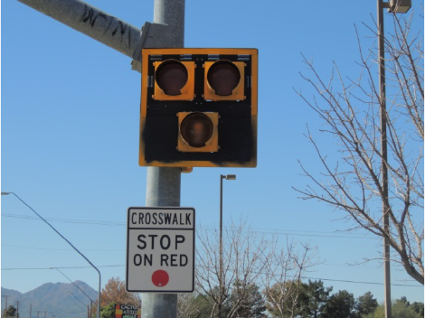
111
The cities of Tucson, AZ and, Austin, TX, had the greatest variety in site characteristics of
interest to this project and were selected for the study. Differences in practices between the
two cities include the following:
• The Tucson, AZ, PHB faces had back plates with yellow reflective borders (see
figure 53), while the Austin, TX, PHB faces did not have back plates (see figure 54).
• The signs used at most of the Tucson, AZ, sites included the CROSSWALK STOP ON
RED (symbolic circular red) (R10-23) sign (see figure 55) and an internally illuminated
PEDESTRIAN CROSSING or CROSSWALK sign (see figure 56). The sign used at the
crossing for the Austin, TX, sites is shown in figure 57. This sign was selected to help
educate drivers regarding appropriate behavior during the flashing red. Recently, FHWA
has received numerous inquiries regarding how to address comprehension issues with the
flashing red phase and is now recommending that if an alternative legend to the R10-23
sign is used, that it be the sign shown in figure 58.
• In advance of the crossing, Tucson, AZ, frequently installed a pedestrian crossing
warning sign (W11-2) (see figure 59). School crossing signs were used at school sites.
• Austin, TX, included the STOP HERE ON RED (R10-6, R10-6a) sign at the stop line.
• The red clearance time (i.e., the elapsed time between start of the vehicular steady red
indication and start of the pedestrian walk indication) was 1 s at the Tucson, AZ, sites and
2 s at the Austin, TX, sites.
• The steady red interval was 8 s for Tucson, AZ, sites and ranged between 9 and 12 s for
the Austin, TX, sites.
• When the Tucson, AZ, sites had a median, a PHB face and a CROSSWALK STOP
ON RED (symbolic circular red) (R10-23) sign was frequently included on a post in
the median.
Figure 55. Photo. Example of sign used in Tucson, AZ.

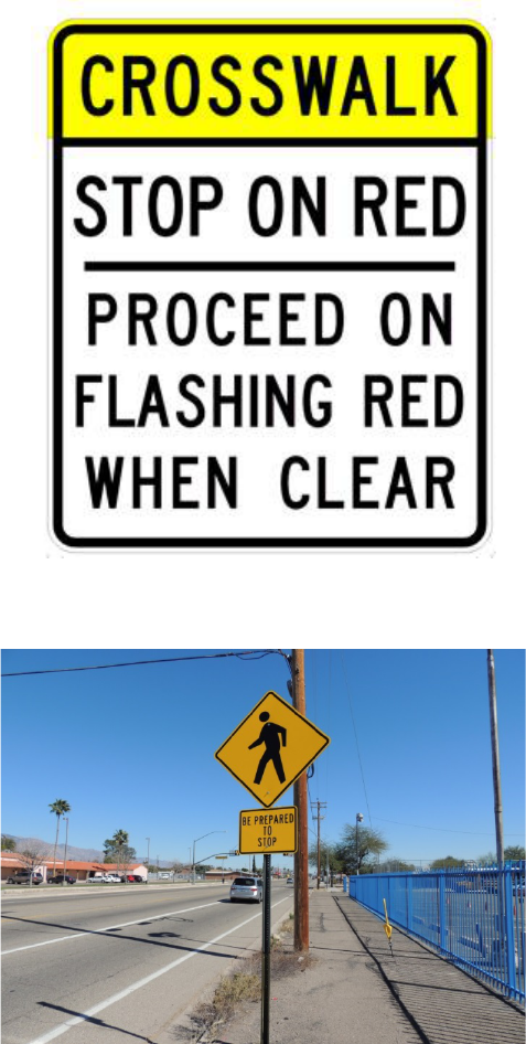
113
Figure 58. Photo. Sign recommended by FHWA to address comprehension issues with the
flashing red phase.
Figure 59. Photo. Example of advance warning sign used in Tucson, AZ.
The crosswalk markings were always located on only one side of the intersection. The PHBs had
between 3 and 4 s of flashing yellow and between 3 and 4 s of steady yellow, consistent with city
policies regarding clearance intervals at signalized intersections. For both cities, the flashing red
duration varied based on the site’s crossing width and ranged from 15 to 29 s.
DATA COLLECTION AND REDUCTION
Data using a multiple video camera setup were collected in November 2014 for the Austin, TX,
sites and in February 2015 for the Tucson, AZ, sites. All observations were collected during
daytime dry weather conditions between 6:30 a.m. and 6:30 p.m. The observers and the video
114
recording device were placed to be inconspicuous from the pedestrians, bicyclists, and motorists.
The goal was to record a minimum of 50 pedestrian crossing events or 4 h of data (the smaller of
the two) at each location, where each crossing event consisted of one or more pedestrian(s)
crossing the entire width of the street. If it appeared that fewer than 50 pedestrian crossing events
would occur within the 4-h block, research team members would cross the street to increase the
sample size of pedestrian crossings. Additional information on the staged pedestrian protocol is
available in Characteristics of Texas Pedestrian Crashes and Evaluation of Driver Yielding at
Pedestrian Treatments.
(35)
The research team members sought to complete data collection efforts
at two sites per day, accounting for travel time between sites and the need to notify local
stakeholders (e.g., school personnel) of their activity. Hence, the periods of peak vehicle and
pedestrian volumes were not necessarily observed.
The video footage was reviewed in several rounds to extract the required observations for
analysis. After the first two rounds, a list of vehicle arrivals, pedestrian arrivals, pedestrian
departures, and PHB actuations was assembled and sorted by site and time. The beacons and
pedestrian signal indications were determined for each event in this list through a series of
computations using the timestamps and the known timing parameters for each PHB.
In the next rounds of video footage review, the computed beacon indications were verified, and
additional detailed observations were extracted including the following:
• Vehicle position relative to the pedestrian for vehicles arriving on a steady or flashing red
beacon indication.
• Driver yielding behavior during steady or flashing red beacon indication.
• Button presses by arriving pedestrians.
• Categorization of pedestrians as staged or non-staged.
• Conflict occurrences.
• Recording whether each driver arriving on steady or flashing red stopped before
proceeding through the crosswalk.
• Recording whether drivers stayed stopped throughout the flashing red indication.
Additional efforts were also undertaken to record any instances of major street vehicles stopping
while the beacon indication was dark as well as to identify minor road driver behaviors during a
beacon actuation. The final dataset reflected over 78 h of video data and included 1,149 PHB
actuations and 1,979 pedestrians who crossed the street.
DRIVER BEHAVIOR FINDINGS
Driver Behavior During Dark Indication
Selected videos were reviewed to identify each occurrence when a vehicle stopped at the
crossing when the PHB was displaying a dark indication. There were several events; however, in
115
almost all cases, it was because of congestion. There were a few cases where the driver stopped
because of a bus or truck loading/unloading or because a pedestrian was in the crosswalk.
Therefore, none of the drivers who stopped at the crossing when the PHB was dark appeared to
be confused regarding the device.
Driver Position Relative to Pedestrian Position During Steady or Flashing Red Indications
When the Driver Drove Across the Crosswalk
The position of the driver and the pedestrian for each driver that drove across the crosswalk
during a steady or flashing red indication was identified. Figure 60 provides an illustration of
driver and pedestrian positions for a crossing. For each cycle and for each approach, the number
of cycles by approach where a given pedestrian-vehicle position combination occurred was
counted. Table 62 summarizes the findings for the 1,252 cycle approaches (1,149 cycles plus
103 cycles where pedestrians were crossing in both directions) for the 20 sites included in the
study. The pedestrian positions were (1) edge of the street clearly indicating the desire to cross,
(2) within the crosswalk on the initial approach (or first half of the crossing), or (3) within the
crosswalk on the second approach (or second half of the crossing). The vehicle was either on the
same approach as the pedestrian or the other approach relative to the pedestrian.
As an example, if a pedestrian was crossing a street that was oriented north and south and was on
the initial approach (say the southbound approach), and if the vehicle was on the other approach,
then the vehicle would be on the northbound approach. In this example, the northbound vehicle
can legally enter the crosswalk during the flashing red portion of the cycle while the pedestrian is
walking eastbound and crossing the southbound approach. Both Arizona and Texas State laws
indicate that vehicles must yield the right-of-way to pedestrians within a crosswalk that are in the
same half of the roadway as the vehicle. So drivers in cases A to F in table 62 would be
considered as not yielding to the pedestrian. Both States also indicate that vehicles are to yield
right-of-way if a pedestrian is approaching closely enough from the opposite side of the roadway
to constitute a danger. Cases G and H in table 62 could possibly fit this situation; however, in the
opinion of those reducing the data, these observations did not have the pedestrian that close to
the vehicle approaching from the other approach. For all those observations, the vehicle on the
other approach entered the crosswalk shortly after the steady red indication had started and the
pedestrian had recently left the curb. A driver entering the intersection during the steady red
indication would be in violation of the beacon indication. Cases A, C, E, G, and I reflect
combinations when the driver would be in violation of the beacon.
For those cases when the driver should yield, the combination with the most yielding violations
was when the pedestrian was at the edge of the street and the drivers entered the crosswalk on the
steady red indication. Case A occurred for 7.7 percent of the observed cycle approaches (96 of
1,252). Most of these non-yielding (and violation) events occurred soon after the beacon changed
to steady red. While it could be argued that a vehicle was not required to yield to the pedestrian
in this situation since the pedestrian was not on the pavement, in the research team’s opinion the
pedestrians in these situation were clearly communicating the intent to cross and were not on the
pavement due to safety concerns. Of course, these drivers were clearly in violation of the steady
red indication. While the research team included cases A and B in the non-yielding counts, the
counts are shown in table 62 so readers can draw their own conclusions. Few, but not zero as
preferred, cycles had a driver entering the crosswalk when the pedestrian was on the same
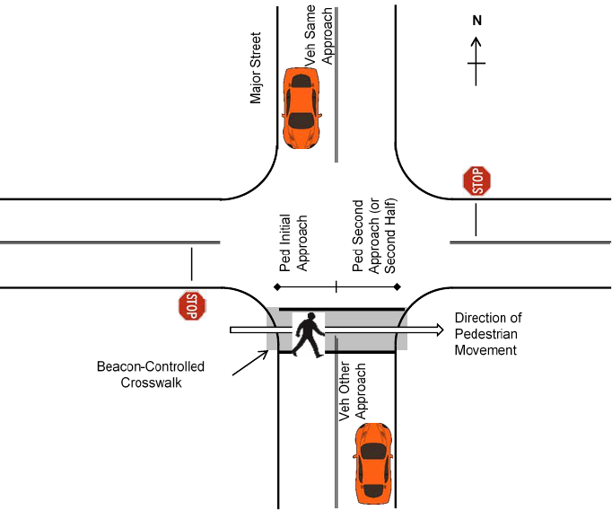
116
approach (see cases B to F). Reviewing the situations when a vehicle enters the crosswalk when
the pedestrian is in the second half of their crossing (see cases E and F) revealed several
occurrences when the vehicles entered the crosswalk soon after the pedestrian departed the lane.
Figure 60. Illustration. Pedestrian and driver positions when the pedestrian is on the initial
approach and vehicles are present on the same approach and on the other approach.

117
Table 62. Pedestrian position and vehicle approach during steady or flashing red
indications.
Case
Pedestrian Position
Vehicle
Approach
a
Beacon
Indication
Percent of
Cycles
Approaches
b
Non-Yielding
and/or
Violation
A
Initial approach, edge of
street
Same
Steady red
7.7
Non-yielding
d
;
violation
B
Initial approach, edge of
street
Same
Flashing red
0.0
Non-yielding
C
Initial approach, moving
within crosswalk
Same
Steady red
0.4
Non-yielding;
violation
D
Initial approach, moving
within crosswalk
Same
Flashing red
0.2
Non-yielding
E
Second approach, moving
within crosswalk
Same
Steady red
0.2
Non-yielding;
violation
F
Second approach, moving
within crosswalk
Same
Flashing red
1.7
Non-yielding
G
Initial approach, moving
within crosswalk
Other
Steady red
8.8
Violation
H
Initial approach, moving
within crosswalk
Other
Flashing red
0.2
Neither
I
Second approach, moving
within crosswalk
Other
Steady red
1.0
Violation
J
Second approach, moving
within crosswalk
Other
Flashing red
23.6
Neither
a
Pedestrian and vehicle positions are relative to where the pedestrian started the crossing (see figure 60 for an example).
b
Results reflect the percent of the 1,252 cycle approaches when the combination of pedestrian and vehicle position occurred.
The total number of cycle approaches (1,252) reflect 1,149 cycles plus 103 cycles when pedestrians were crossing in both
directions for the 20 sites included in the study.
c
Demonstrates whether this case reflects a non-yielding driver and/or a violation of the red indication.
d
While it could be argued that a vehicle is not required to yield to the pedestrian in this situation since the pedestrian was not
“on the pavement,” the pedestrians in these situation were clearly communicating the intent to cross and remained on the curb
rather than on the pavement due to safety concerns. These drivers were in violation of the steady red indication.
Driver Yielding Behavior During Steady or Flashing Red Indications
For each pedestrian crossing when the PHB was showing steady or flashing red, the number of
drivers that yielded and did not yield was determined. The driver yielding rates reflected all
available pedestrian crossings regardless of whether the pedestrian was a member of the research
team. A driver was considered to have not yielded to the pedestrian if the driver crossed the
crosswalk markings when the PHB was in either the steady red or flashing red indications and
the pedestrian was at the edge of the street clearly communicating to drivers the intent to cross or
was walking on the same approach as the driver. When the crossing pedestrian was a member of
the research team, the team member would place a foot on the pavement to clearly communicate
the intent to cross. Using only staged pedestrian crossings would have required a much longer
data collection period per site because of the large number of pedestrians crossing at the
intersections. Therefore, the study included non-staged pedestrians. If it appeared that the

118
non-staged pedestrian was not clearly communicating the intent to cross, perhaps by not standing
near the edge of the sidewalk, the pedestrian crossing was not included in the study.
Counting the number of vehicles that did or did not yield to a crossing pedestrian was easier with
video data when compared to gathering the data in the field. The video could be replayed to
determine the exact position of a vehicle when the signal indication changed. In addition, the
video allowed for greater consistency between data collectors, as an event could be reviewed by
more than one person. Table 63 provides the driver yielding values for the 20 sites. Overall,
driver yielding for these 20 sites averaged 96 percent. In almost all of the crossings, drivers
appropriately yielded to the crossing pedestrians.
Table 63. Driver yielding values for all 20 sites.
Site
Number
of PHB
Actuations
Number
of Drivers
Yielding
Number of
Drivers Not
Yielding
Driver
Yielding
(Percent)
a
TU-003
19
54
3
95
TU-004
49
162
4
98
TU-007
60
183
5
97
TU-021
52
131
7
95
TU-037
74
248
8
97
TU-042
71
187
6
97
TU-059
55
151
0
100
TU-070
52
159
4
98
TU-072
51
230
5
98
TU-073
70
368
19
95
TU-090
28
61
0
100
TU-091
30
67
4
94
AU-04
62
147
9
94
AU-07
95
256
11
96
AU-11
60
169
26
87
AU-16
71
195
6
97
AU-21
52
139
5
97
AU-22
70
171
4
98
AU-24
97
182
9
95
AU-27
31
99
10
91
Total
1,149
3,359
145
96
a
Driver yielding = Percent of approaching drivers who should have yielded and did so.
When reviewing the results by city, Tucson, AZ, had an average yielding rate of 97 percent
while Austin, TX, had an average yielding rate of 94 percent. Affecting the average result for
Austin, TX, were two sites: AU-11 and AU-27. Almost all of the non-yielding vehicles at
AU-11 were northbound vehicles that crossed the crosswalk very soon after the PHB turned
steady red and frequently moved at lower speeds due to high vehicle volumes present or due to
an active reduced speed limit for the school zone. At AU-27, about half of the non-yielding
vehicles entered the crosswalk very soon after the PHB turned to steady red (six vehicles), with
the remaining non-yielding vehicles (four vehicles) entering the crosswalk before the pedestrian
119
completely cleared that half of the roadway. Other potential differences between Austin, TX, and
Tucson, AZ, that could affect yielding rates could be the length of time the PHB treatment has
been used in the city (they have been in Tucson, AZ, for many more years than Austin, TX), the
use of back plates (common in Tucson, AZ, not in Austin, TX), beacon face mounting locations
(Tucson, AZ, typically mounted one face over the approach, one to the right of the approach, and
one in the median if a raised median was present, while Austin, TX, typically mounted two faces
over the approach), and the use of supplemental signs on the mast arm (Tucson, AZ, sites
typically included a CROSSWALK or PEDESTRIAN CROSSWALK sign in addition to the
regulatory CROSSWALK STOP ON RED (symbolic circular red) (R10-23) sign while
Austin, TX, used a combination sign that provided the additional information of STOP ON
FLASHING RED (symbolic flashing circular red) THEN PROCEED IF CLEAR).
There were different driver behaviors within those situations when drivers did not yield to the
pedestrians. Reviewing the conditions when drivers were non-compliant revealed that several of
the non-compliant drivers entered the crossing just after the PHB changed from steady yellow to
steady red and the pedestrian was at the edge of the street. Given that these drivers were provided
with at least 7 to 8 s of warning by way of the flashing and steady yellow indications, and based
on the posted speed limits for these sites (30 to 45 mi/h), the drivers did have sufficient warning
to stop upstream of the crossing but decided not to stop. In a few of the cases, the driver
proceeded through the crosswalk just after the pedestrian had cleared the lane.
Driver Behavior During Flashing Red Indication
For about 20 percent of the observed PHB actuations, vehicles were not present during the
flashing red indication. When a queue of vehicles was present during the flashing red indication,
about half of the crossing actuations included at least one driver who did not completely stop
prior to entering the crosswalk. About 5 percent of the actuations included at least one driver
who stopped on the flashing red indication and remained stopped until the dark indication. This
behavior was observed at about the same frequency in both cities. In some cases, these drivers
might not have realized that they could proceed after stopping if their half of the crosswalk was
clear of pedestrians. However, there were many cases where the stopped drivers could not
proceed for one or more of the following reasons:
• The driver arrived in the last few seconds of the flashing red indication.
• The driver’s half of the crosswalk was continually occupied by pedestrians, some of
whom may have been slow or may have started their crossing after the start of the
flashing red indication (i.e., during their flashing do not walk indication).
• Minor movement drivers were proceeding without complying with their requirements
to stop.
Impact of PHB Actuation on Minor Movement Drivers
Interested practitioners have raised questions about how PHBs affect minor movements that do
not pass through the beacon-controlled crosswalk. These movements may include one left-turn
movement originating from the major street (LT), up to two through movements on the
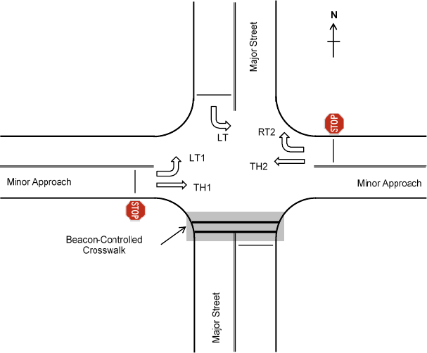
120
minor-street approaches (TH1 and TH2), a left-turn movement originating from the minor street
(LT1), and a right-turn movement originating from the minor street (RT2). These movements are
illustrated in figure 61. Specifically, the following questions have been asked:
• When the PHB is active, do minor movement drivers take advantage of the gaps that have
been created in the major street traffic and complete their movements more easily?
• When the PHB is showing the flashing red indication, does the intersection function like
a four-way stop-controlled intersection?
Figure 61. Illustration. Minor movements at a PHB-controlled crosswalk.
The research team conducted a review of the video footage to answer these questions. The
review included 17 of the 20 PHB sites. Sites TU-091, AU-07, and AU-27 were excluded
because they lacked the relevant movements due to site layout (midblock crossing, stop line
located well downstream of the movement, or the movement is prohibited) or the movements
existed but were negligible in volume. Not all minor movements were present at every site
because some of the sites were three-legged intersections or the fourth leg was a driveway
with minimal traffic (e.g., TU-070). The minor movements permitted at the sites are listed in
table 64.

121
Table 64. Minor movements permitted at the sites.
Movements Present
Sites
LT, LT1, TH1, TH2, and RT2
(four-legged intersection)
TU-003, TU-021, TU-037, TU-042,
TU-059, TU-072, TU-073, TU-090,
AU-04, AU-16, and AU-24
LT and LT1 (three-legged intersection)
TU-004, TU-070, and AU-11
LT and RT2 (midblock site with
nearby driveway)
AU-21 and AU-22
A total of 850 minor movement vehicles were observed. This set of vehicles includes only those
that arrived and/or departed while the PHB was active (i.e., not displaying the dark indication).
The vehicle distribution by site and movement code is provided in table 65. Note that the pairing
of the LT and RT2 movements represents a significant portion of the sample size, particularly at
sites TU-042, TU-072, TU-073, AU-21, and AU-22. These movements at these sites represent
about 62 percent of the sample size (525 of 850 vehicles). Additional turning movements were
possible but not included in the minor movement analysis. Turning vehicles that originated from
the minor approaches and passed through the crosswalk are included in the other analyses
documented in this chapter.
Table 65. Minor movement vehicle distribution by site.
Site
Movement Code
LT
LT1
RT2
TH1
TH2
Total
TU-003
2
1
0
0
0
3
TU-004
10
0
7
0
0
17
TU-007
3
0
3
0
0
6
TU-021
3
13
8
4
6
34
TU-037
4
7
10
4
1
26
TU-042
154
2
116
11
0
283
TU-059
9
34
3
6
3
55
TU-070
0
10
0
0
0
10
TU-072
30
7
18
5
3
63
TU-073
27
3
46
1
0
77
TU-090
0
13
1
2
0
16
AU-04
8
17
9
2
0
36
AU-11
0
21
0
0
0
21
AU-16
0
8
0
0
0
8
AU-21
13
0
42
0
0
55
AU-22
28
0
51
0
0
79
AU-24
12
42
2
2
3
61
Grand Total
303
178
316
37
16
850
The vehicle distribution by movement code and PHB indication on vehicle arrival is provided in
table 66. Arrival is defined as the time that the vehicle stopped at the stop line on its approach or
the time that the vehicle crossed the stop line if it did not stop. The vehicle distribution by
movement code and PHB indication on its departure is provided in table 67. Departure is defined
as the time that the vehicle exited the intersection.

122
Table 66. Minor movement vehicle distribution upon vehicle arrival.
Movement
Code
PHB Indication
Dark
Flashing
Yellow
Steady
Yellow
Steady
Red
Flashing
Red
Total
LT
31
1
14
85
172
303
LT1
41
3
12
54
68
178
RT2
32
4
15
79
186
316
TH1
14
1
2
8
12
37
TH2
7
0
1
3
5
16
Grand Total
125
9
44
229
443
850
Table 67. Minor movement vehicle distribution upon vehicle departure.
Movement
Code
PHB Indication
Dark
Flashing
Yellow
Steady
Yellow
Steady
Red
Flashing
Red
Total
LT
33
0
3
107
160
303
LT1
22
0
0
89
67
178
RT2
39
0
1
111
165
316
TH1
4
0
0
22
11
37
TH2
1
0
0
11
4
16
Grand Total
99
0
4
340
407
850
As shown by the total count numbers in the rightmost columns of table 66 and table 67, the
turning movements were the most commonly observed movements, especially movements LT
and RT2, which were complementary. The through movements were less common, partly
because these movements did not exist at the three-legged intersection sites.
The total count numbers in the bottom rows of table 66 and table 67 generally reflect the
proportion of time that the PHB was active. The number of vehicles arriving or departing on the
dark indication is small because vehicles that both arrived and departed on the dark indication
were excluded from this analysis.
The distribution of minor movement vehicles by PHB indication upon arrival and PHB
indication upon departure is shown in table 68. As shown, most vehicles departed on either
steady red or flashing red regardless of when they arrived. However, a small number of vehicles
experienced notable delay because they arrived while the PHB was active but could not depart
until the next dark indication. Specifically, nine vehicles arrived during flashing red but did not
depart until the steady yellow or steady red indication during the next PHB actuation. These long
delays occurred during periods when the major street volume was sufficiently high enough that
no acceptable turning or crossing gaps were available during the dark indication, and the major
street drivers were aggressive during the flashing red indication such that they either did not
stop consistently or stopped briefly and proceeded without waiting for other drivers’ movements
to proceed.

123
Table 68. Minor movement vehicle distribution by PHB indication.
PHB
Indication
Upon Arrival
PHB Indication Upon Departure
Dark
Flashing
Yellow
Steady
Yellow
Steady
Red
Flashing
Red
Total
Dark
0
0
0
108
17
125
Flashing yellow
0
0
0
8
1
9
Steady yellow
0
0
0
39
5
44
Steady red
5
0
0
180
44
229
Flashing red
94
0
4
5
340
443
Grand Total
99
0
4
340
407
850
To examine stop compliance, drivers were classified as violators under the following conditions:
• The driver was making the LT movement, arrived during a steady or flashing red
indication, and did not stop. At all sites, the stop line was marked across all through and
left-turn lanes, such that these drivers were required to stop even though they do not pass
through the crosswalk.
• The driver was making the LT1, TH1, TH2, or RT2 movement and did not stop. In other
words, the driver failed to stop at the STOP sign.
Each driver in the database was thus classified as a violator or non-violator, and violation rates
were computed for each site based on the amount of video footage that was collected at the site
(i.e., violations per hour). These findings are shown in table 69. The percentage of drivers not
stopping varied widely, from 30.8 to 89.9 percent. Many of these percentages were computed
based on the small number of minor movement vehicles that were observed while the PHBs were
active. In terms of rate, violations at most sites were less common than five violations/h (or
one violation every 12 min).

124
Table 69. Minor-movement violation rates by site.
Site
Number of
Vehicles
Percent Not
Stopping
Violation Rate
(Violations/h)
TU-003
3
33
0.4
TU-004
17
65
2.6
TU-007
6
33
0.5
TU-021
34
32
2.2
TU-037
26
31
1.9
TU-042
283
72
46.7
TU-059
55
60
7.2
TU-070
10
60
1.5
TU-072
63
33
3.9
TU-073
77
42
7.5
TU-090
16
44
1.6
AU-04
36
64
6.3
AU-11
21
52
3.0
AU-16
8
38
0.8
AU-21
55
49
10.2
AU-22
79
90
40.6
AU-24
61
39
5.4
The following seven sites were found to have violation rates in excess of five violations/h:
TU-042, TU-059, TU-073, AU-04, AU-21, AU-22, and AU-24. A more focused examination of
these sites was conducted by computing violation rates for each movement. The results of this
examination are shown in table 70. Similar computations were performed for all movements at
all sites, but none of the movements omitted from table 70 had violation rates higher than
four violations/h.

125
Table 70. Selected minor-movement violation rates by site and movement code.
Site
Movement
Code
Number of
Vehicles
Percent
Not Stopping
Violation Rate
(Violations/h)
Notes
TU-042
LT
154
72
25.4
Entering a collector near a
high school campus
RT2
116
77
20.4
Exiting a collector near a
high school campus
TU-059
LT1
34
56
4.2
Exiting a residential
neighborhood with a nearby
elementary school campus
TU-073
RT2
46
46
4.9
Exiting a residential
neighborhood with a nearby
high school campus
AU-04
LT1
17
88
4.1
Exiting a collector near a
supermarket
AU-21
RT2
42
48
7.8
Exiting a supermarket
AU-22
LT
28
96
15.4
Entering a supermarket
RT2
51
86
25.2
Exiting a supermarket
AU-24
LT1
42
43
4.1
Exiting a supermarket
All of the movements listed in table 70 were located close to major traffic generators such as
schools or supermarkets. In fact, the majority of the violations observed at site TU-042 occurred
in the morning period before classes began for the day. Violations were also frequent at site
AU-22; however, it should be noted that the LT movement at this site occurred from a TWLTL,
and the stop line for the PHB was marked in the adjacent through lanes but not in the TWLTL,
suggesting that the stopping requirement might not have been intended for this movement. This
marking practice differed from the practice at other Austin, TX, sites, where stop lines were
extended through all approach lanes. Sites AU-21 and AU-22 were similar in that their LT and
RT2 movements went into or out of supermarkets, but the LT movement at site AU-22 did not
have a high violation rate. The major street at this site was a four-lane undivided city arterial, so
left-turning drivers did not have a turn bay and were often blocked from completing the LT
movement while the PHB was active.
Based on the preceding information, the following observations could be made:
• Minor movement drivers took advantage of gaps that were created in the major street
traffic while the PHBs were active.
• PHB sites did not necessarily operate like four-way stops while the flashing red
indication was shown. At sites near major traffic generators, movements entering or
exiting the traffic generator tended to dominate the operation of the intersection, and stop
compliance for these movements tended to be low.
These trends may occur at any type of unsignalized pedestrian crossing treatment while
pedestrians are present. They are likely not unique to PHB-controlled crossings.

126
PEDESTRIAN BEHAVIORS FINDINGS
Pedestrian Departures by Indication
Of the 1,979 pedestrians crossing the street, 290 were research team members who always
crossed when the beacons showed steady or flashing red to the motorists. Most of the remaining
1,689 general public pedestrians departed when the beacon showed a steady red indication to
the drivers. As shown in table 71, 80 percent departed during the steady red or flashing red
indications. Approximately 13 percent of the pedestrians departed while the PHB was still in the
vehicle clearance intervals.
Table 71. Pedestrian departures by indication.
Site
Dark
Flashing
Yellow
Steady
Yellow
Steady
Red
Flashing
Red
Total
TU-003
0
1
1
11
1
14
TU-004
0
1
13
58
5
77
TU-007
1
0
5
47
3
56
TU-021
3
1
6
53
1
64
TU-037
6
0
5
66
5
82
TU-042
22
2
18
101
12
155
TU-059
0
1
4
21
4
30
TU-070
3
0
2
18
3
26
TU-072
*
16
0
9
57
0
82
TU-073
1
1
0
77
12
91
TU-090
2
0
3
3
0
8
TU-091
4
0
0
10
0
14
AU-04
6
4
4
44
5
63
AU-07
a
20
6
22
132
18
198
AU-11
0
0
2
47
22
71
AU-16
1
2
2
86
3
94
AU-21
1
3
20
73
7
104
AU-22
7
10
28
123
22
190
AU-24
28
10
16
130
25
209
AU-27
3
1
3
46
8
61
Grand Total
(Percent)
124 (7)
43 (3)
163 (10)
1,203 (71)
156 (9)
1,689 (100)
a
The PHB was located within the coordinated corridor where the timing of when the PHB was active was
influenced by the nearby coordinated signals.
For the pedestrian crossings observed that did not include the research team member crossings,
only 124 pedestrians (7 percent) left during the dark indication. For the majority of these
pedestrians, the roadway volume was such that the pedestrian was able to find sufficient gaps to
cross. The volume per minute per lane was less than four vehicles/min/lane for the majority of
these crossings. Figure 62 shows the cumulative distributions of the 1 min/lane volume for those
pedestrians that departed during the dark indication (i.e., blue dashed line) and those that
departed during an active indication (i.e., red solid line). Pedestrians were more likely to wait for
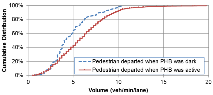
127
the PHB to be active before starting to cross at the higher roadway volumes, as shown by the
location of the red solid line to the right of the blue dashed line. For example, the cumulative
distributions reached the value of 80 percent at volumes of about six vehicles/min/lane for the
blue dashed line and about eight vehicles/min/lane for the red solid line. This trend shows that
only 20 percent of non-compliant pedestrians were still willing to cross if the roadway volume
exceeded six vehicles/min/lane (i.e., 1,440 vehicles/h at a four-lane site). Less than 5 percent of
non-compliant pedestrians crossed when the roadway volume exceeded 10 vehicles/min/lane.
Conversely, roughly half of the compliant pedestrians crossed at roadway volumes exceeding
six vehicles/min/lane.
Figure 62. Graph. Volume cumulative distribution when pedestrian started the crossing.
Two of the PHB sites were located within coordinated corridors where the timing of PHB
activation was influenced by the nearby coordinated signals. The other 18 sites were at “hot
button” sites, where the PHB sequence starts following the push of the pushbutton. About
one-third of the pedestrians (36 of 124) who departed during the dark indication were at the sites
where the PHB is coordinated with nearby signals. While a large value, there were other sites
with more pedestrians departing during the dark indication, both in terms of number of
pedestrians and proportion of pedestrians observed at the site. The percentage of pedestrians
departing during the dark indication was 13 percent at the coordinated sites and 6 percent at the
hot button sites. Departures on dark were much less frequent at the coordinated site that had
pedestrian pushbuttons with red lights that illuminate when the button is pressed. The
coordinated site with the red-lighted buttons had 10 percent of pedestrians departing on dark,
while the coordinated site with the non-lighted buttons had 20 percent of pedestrians departing
on dark.
Pedestrian Actuation of the PHB
Of the 1,979 pedestrians crossing the street, 290 were research team members who crossed using
a staged pedestrian protocol and always activated the PHB. The remaining 1,689 general public
pedestrians were coded by whether they pushed the pedestrian pushbutton or did not push the
pushbutton subdivided by whether the PHB was already active or not active when they arrived to

128
the crossing. Table 72 shows the number of pedestrians by action. Overall, most pedestrians
(average of 91 percent) who could have activated the PHB did. As can be seen in table 72, there
were some sites with lower percent actuations (e.g., AU-04) and other sites where every
pedestrian crossed with an activated PHB (e.g., TU-03, TU-04, and AU-11).
Table 72. Number of pedestrians by site who pushed, did not push, or did not push because
PHB was active.
Site
Pushed
Did Not
Push
Did Not Push;
Already
Active
Total
Number of
Pedestrians
Percent
a
TU-003
13
0
1
14
100
TU-004
73
0
4
77
100
TU-007
55
1
0
56
98
TU-021
61
2
1
64
97
TU-037
75
6
1
82
93
TU-042
116
21
18
155
85
TU-059
29
1
0
30
97
TU-070
21
3
2
26
88
TU-072
b
66
14
2
82
83
TU-073
62
13
16
91
83
TU-090
6
2
0
8
75
TU-091
12
2
0
14
86
AU-04
43
14
6
63
75
AU-07
b
165
14
19
198
92
AU-11
49
0
22
71
100
AU-16
90
1
3
94
99
AU-21
97
2
5
104
98
AU-22
147
11
32
190
93
AU-24
162
25
22
209
87
AU-27
55
3
3
61
95
Grand Total
1,397
135
157
1,689
91
a
Percent = Percentage reflecting the ratio of the number of pedestrians that pushed the button to the
number of pedestrians that if they would have pushed the button would have triggered a change in
the device (i.e., those that pushed and those that did not when the device was dark). In other words,
this column does not include those pedestrians who arrived when the PHB was active.
b
The PHB was located within coordinated corridor where the timing of when the PHB was active was
influenced by the nearby coordinated signals.
A plot of the percentage of pedestrians who activated the PHB when arriving to the crossing
when the PHB was not already active is shown by posted speed limit in figure 63, by crossing
distance in figure 64, and by hourly volume in figure 65 . A review of these plots shows trends
for the highest values. A high number of pedestrians (93 percent) activated the device on the
45-mi/h posted speed limit road. For the 40-mi/h or less roads, a large range of actuation was
observed—between 75 and 100 percent. The percentage of pedestrians pushing the button was
always greater than 83 percent for the longer crossing distances (i.e., longer than 110 ft).

129
The 1-min volume count nearest to the arrival time of the pedestrian was determined. The
number of pedestrians by their action was summed for each 1-min count value for all 20 sites.
The 1-min counts with less than 20 pedestrians crossing were omitted for the plot shown in
figure 65. The 1-min count was adjusted to an hourly equivalent value by multiplying the 1-min
count by 60. When the hourly volume for both approaches was 1,500 vehicles/h or more, the
percent of pedestrians activating the PHB was always 92 percent or more.
Figure 63. Graph. Percentage of pedestrians pushing the button, by posted speed limit.
Figure 64. Graph. Percentage of pedestrians pushing the button, by crossing distance.
Figure 65. Graph. Percentage of pedestrians pushing the button, by 1-min volume counts
adjusted to hourly counts.

130
Some of the pedestrians who activated the PHB departed prior to the walk indication. The
beacon indication when the pedestrian departed is shown in table 73. Most of the pedestrians
who departed after pushing the pushbutton either left during the steady red (82 percent) or the
flashing red (2 percent). About 1 percent of those who activated the device left while the device
was still dark, with most occurring at the two locations where the PHB was within a coordinated
corridor (sites TU-072 and AU-07).
Table 73. Indication when pedestrian departed for those that activated the PHB.
Site
Dark
Flashing
Yellow
Steady
Yellow
Steady Red
Flashing
Red
Total
TU-003
0
1
1
11
0
13
TU-004
0
1
13
58
1
73
TU-007
0
0
5
47
3
55
TU-021
0
1
6
54
0
61
TU-037
0
0
5
66
4
75
TU-042
0
2
18
96
0
116
TU-059
0
1
4
21
3
29
TU-070
0
0
2
18
1
21
TU-072
a
5
0
8
53
0
66
TU-073
0
1
0
60
1
62
TU-090
0
0
3
3
0
6
TU-091
2
0
0
10
0
12
AU-04
0
4
4
35
0
43
AU-07
a
6
6
22
129
2
165
AU-11
0
0
2
47
0
49
AU-16
0
2
2
86
0
90
AU-21
0
3
20
70
4
97
AU-22
1
9
28
109
0
147
AU-24
3
10
16
129
4
162
AU-27
0
1
3
46
5
55
Grand Total
(Percent)
17
(1.2)
42
(3.0)
162
(11.6)
1,148
(82.2)
28
(2.0)
1,397
(100)
a
The PHB was located within coordinated corridor where the timing of when the PHB was active was
influenced by the nearby coordinated signals.
CONFLICTS FINDINGS
All occurrences of pedestrian/vehicle conflicts and erratic maneuvers were noted when observed
in the video footage. A conflict is defined based on the following criteria:
• The vehicle suddenly changes path, speed, or both.
• The vehicle’s brake lights illuminate unexpectedly during a turning maneuver.
• The pedestrian exhibits one or more of the following behaviors:
o Slows down due to vehicle presence.

131
o Stops and waits for the vehicle to pass through the crosswalk.
o Steps sideways to avoid a vehicle.
o Runs or speeds up to avoid a vehicle.
o Turns back to origin curb to avoid a vehicle.
o Makes another sudden change in path or speed in response to an
approaching vehicle.
In the 78 h of video footage, 54 conflicts were observed. The distribution of the conflicts
categorized by vehicle maneuver was 38 for through vehicles, 10 for left-turning vehicles, and
6 for right-turning vehicles. Distribution by vehicle maneuver was analyzed because of concerns
about turning traffic operations while the PHB was serving pedestrians. While major street
through vehicles were stopped by the PHB, turning drivers originating from the minor
approaches could see significant gaps form on the major street and may have taken this
opportunity to turn, possibly leading to conflicts with pedestrians in the crosswalk.
The conflicts were tabulated by vehicular beacon indication and vehicle maneuver, as shown in
table 74. Beacon indication can be used to classify pedestrians as compliant (i.e., they departed
the corner on a steady red indication while the walk indication was displayed) or non-compliant
(i.e., they departed on one of the other beacon indications while the flashing or steady do not
walk indication was displayed). Slightly less than half of the observed conflicts occurred during
the dark beacon indication and involved a through vehicle. These conflicts usually involved
pedestrians who either crossed without pushing the button or pushed the button but did not wait
for the walk indication and then paused in the raised curb median while crossing. The latter case
occurred most frequently at site TU-072 (14 conflicts), which had 6 lanes and operated in
coordinated mode.
Table 74. Vehicle and pedestrian conflicts by beacon indication and vehicle maneuver.
Beacon
Indication
Vehicle Maneuver
Through
Left Turn
Right Turn
Total
Dark
a
25
2
0
27
Flashing yellow
a
0
0
0
0
Steady yellow
a
0
1
0
1
Steady red
8
7
6
21
Flashing red
a
5
0
0
5
Total
38
10
6
54
a
Indicates
pedestrians who were not in compliance with signal indication.
A notable number of conflicts involving left-turning vehicles was observed at site AU-21. This
site was located near a well-patronized supermarket and a bus stop, with a driveway located
about 45 ft away from the crosswalk. At that distance, drivers making left turns out of the
supermarket parking lot would be able to turn onto the major street but would still be oriented
diagonally when encountering the crosswalk. Many of these drivers encroached on the crosswalk
while attempting to complete their turning maneuvers, leading to conflicts if pedestrians were

132
present. A similar geometric layout was present at site AU-22, but this site did not exhibit
conflicts because the driveway was located farther away from the crosswalk (about 60 ft) and
afforded left-turning drivers more room to complete their turning maneuvers and wait for
pedestrians to clear.
To account for exposure differences across the sites, conflict rates were computed using
three conflict rate measures, as provided in table 75. The measure of conflicts per pedestrian-
vehicle accounted for the influence of both pedestrian and vehicle exposure. For all three rate
measures, the conflict rate was found to be higher for non-compliant pedestrians than for
compliant pedestrians. These rates were interpreted in terms of total exposure (pedestrians or
vehicles or pedestrian and vehicles). That is, at a site that experiences 100 pedestrians crossing
per hour, it is expected that 2.73 conflicts would be observed per hour, of which 1.06 would
involve compliant pedestrians and 1.67 would involve non-compliant pedestrians.
Table 75. Pedestrian-vehicle conflict rates.
Pedestrian
Group
Conflicts per
100 Observed
Pedestrians
Conflicts per
10,000 Vehicles
All
2.73
4.15
Compliant
1.06
1.61
Non-compliant
1.67
2.54
Notable conflict rates were observed at site TU-072 because of the high number of non-
compliant pedestrians. This site operated in coordinated mode with buttons that did not provide
audible or visual cues indicating that the button press had been registered. As a result, many
pedestrians pushed the button but may have believed that the PHB was malfunctioning or may
have grown impatient while waiting for service and crossed the major street before the walk
indication was displayed. Similar behavior was not observed at site AU-07, which operated in
coordinated mode but with buttons that had small red lights that illuminated when the button
was pressed.
Notable conflict rates for both compliant and non-compliant pedestrians were also observed at
several sites where the PHBs were located near supermarkets and multiple bus stops. At these
sites, many bus riders walked through the supermarket parking lots or ran across the major street
while transferring between bus lines. The presence of bus stops near an access point with
significant turning vehicle volumes tended to result in higher conflict rates.
133
CHAPTER 7. SUMMARY/CONCLUSIONS, DISCUSSION,
AND FUTURE RESEARCH NEEDS
OVERVIEW
This chapter provides summaries and conclusions along with a discussion of the implications of
the findings or each of the studies. The chapter concludes with a list of future research needs.
CLOSED-COURSE STUDY
Summary/Conclusions
The closed-course study was designed to quantify drivers’ ability to detect pedestrians within
and around a crosswalk (a measure of disability glare) and quantify discomfort glare ratings
associated with LEDs in traffic control devices. Participants drove the study vehicle to the
starting location where they parked the vehicle 200 ft from sign assemblies that consisted of a
pedestrian crossing sign with LEDs within the sign face and LEDs in rectangular beacons above
and below the sign. After the driver placed the vehicle into park, they were asked to set occlusion
glasses on their faces. The occlusion glasses obscured the participants’ vision by going opaque
when there was no power supplied to them and going clear when power was supplied.
Once the participants’ vision was occluded, technicians placed a static cutout photo of a
pedestrian (either 54 inches tall to represent a child or 70 inches tall to represent an adult) within
the crosswalk located near the sign assemblies. An experimenter then restored the participants’
vision, and the participants were asked to identify the direction the pedestrian was traveling (to
the left, to the right, or not present) as quickly as possible using a button box. When the
participants pressed the button on the button box, the glasses turned opaque again. Following the
participants’ identification of the pedestrian’s direction, the researcher asked the participants to
rate the intensity of the LED (comfortable, irritating, or unbearable) before asking the field crew
to set up the next condition. This process was repeated for various combinations of LED
brightness, LED locations, pedestrian positions, and flash patterns. This portion of the study was
stationary, and after completion, the participants drove to the check-in location and completed a
laptop survey that asked a series of questions to obtain the participants’ opinions regarding flash
patterns for LEDs used with signs.
To increase the number of flash patterns tested in the study but to keep within a reasonable
testing period, data were collected within two sets. Within each set, two flash patterns were
tested for the LEDs in rectangular beacons and two flash patterns for the LEDs within sign. For
set I, the study was conducted during both daytime and nighttime. For set II, the study was only
conducted during the nighttime. During the testing of set I, it was determined that night was the
more critical condition, which is why only nighttime data were collected during set II.
A summary of the findings for LED intensity and location along with flash pattern is provided in
table 76. Table 77 summarizes the findings for pedestrian height, pedestrian position, and
participant age. Following is an overview of the key findings from this research study.

134
Table 76. Summary of results for LED intensity and location along with flash pattern.
Variable
LED Intensity
Flash Pattern
LED Location
Detection
time
• Night: Detection time was
longer when intensity was
higher—8.5 percent greater
for 2,200 candelas compared
to when the LEDs were off.
• Day: 2.4 percent greater for
2,200 candelas compared to
when LEDs were off.
• Night: 2-5 flash pattern
when used above or below
sign yielded detection
time 6 percent longer
than no flash pattern at
all. Using the wig-wag
pattern above or below
sign resulted in a
13.7 percent increase in
detection time compared
to no flash pattern at all.
• Day: 2-5 flash pattern
when used above or below
sign caused a 5.2 percent
increase in detection time
compared to no flash
pattern at all.
• Night: Detection time was
fastest when LEDs were
above the signs. In
comparison, there was a
6 percent increase in
detection time when
LEDs were within the
sign and 12 percent
increase when LEDs were
below the sign.
• Day: Not statistically
significant.
Detection
accuracy
• Night: Accuracy was lower
when intensity was higher.
Odds of accurate detection
for 2,200 candelas reduced
to 0.58 times the odds for
0 candelas.
• Day: Not statistically
significant.
• Night: Not statistically
significant.
• Day: Not statistically
significant.
• Night: Higher accuracy
when LEDs were above
the sign. In comparison,
odds of accurate
responses for LEDs below
were 0.54 times the odds
for LEDs above.
• Day: Not statistically
significant.
Discomfort
• Night: Discomfort was
higher when intensity was
higher. Odds of increased
discomfort for
2,200 candelas was
9.43 times the odds when
LEDs were off.
• Day: Discomfort was higher
when intensity was higher.
Odds of increased
discomfort for
2,200 candelas was
7.05 times the odds when
LEDs were off.
• Night: When LEDs were
active, the odds of
increased discomfort
were about 8 times the
odds for no LEDs flashing
(statistically significant).
No difference between
either 2-5 or wig-wag
patterns compared to the
rest of patterns. No
difference between 2-5 and
wig-wag patterns.
• Day: Not statistically
significant.
• Night: Odds of higher
discomfort when the
LEDs were below
1.86 times the odds when
LEDs were above. No
difference between within
and above locations.
• Day: Not statistically
significant.
Note: Bold text indicates the results were statistically significant.

135
Table 77. Summary of results for pedestrian height and position and participant age.
Variable
Ped Height
Pedestrian Position
Participant Age
Detection
time
• Night: Detection time was
longer when the
pedestrian was short
rather than tall. There
was a 3.6 percent
detection time increase for
the short pedestrian.
• Day: Detection time was
longer when the
pedestrian was short
rather than tall. There
was a 3.9 percent increase
for the short pedestrian.
• Night: Detection time
shorter for center position
as compared to either side.
• Day: Detection time
shorter for center position
as compared to either side.
• Night: 0.5 percent increase in
detection time per additional
year of driver age.
• Day: 1 percent increase in
detection time per year of
driver age.
Detection
accuracy
• Night: Detection accuracy
was higher when the
pedestrian was tall
compared to short. Odds
of accurate detection for
the short pedestrian were
0.65 times the odds for the
tall pedestrian.
• Day: Detection accuracy
was higher when the
pedestrian was tall
compared to short. Odds
of accurate detection for
the short pedestrian were
0.64 times the odds for the
tall pedestrian.
• Night: Center had more
accurate responses
compared to either side.
Higher accuracy at center
compared to either side.
• Day: Same trend as night,
but evidence is only
suggestive.
• Night: Odds of accurate
detections for oldest
participants (85 years old)
about 0.16 times the odds for
the youngest (21 years old).
• Day: Odds of accurate
detections for oldest
participants (83 years old)
are about 0.04 times the odds
for the youngest
(19 years old). However, this
difference is not practically
significant, since both
accuracy rates for these
participants are above 95%.
Discomfort
• Night: Odds of higher
discomfort for the short
pedestrian were 0.86 times
the odds for the tall
pedestrian.
• Day: Not statistically
significant.
• Night: Odds of higher
discomfort nearly doubled
(i.e., multiplicative factor
of 1.84) when placing
pedestrian at either side,
compared to center of the
crosswalk. No difference in
discomfort level between
pedestrian and no-pedestrian
conditions.
• Day: Not statistically
significant.
• Night: Odds of higher
discomfort changed by a
multiplicative factor of 0.98
with each additional year of
age.
• Day: Not statistically
significant.
Note: Bold text indicates the results were statistically significant.
136
Average nighttime detection time for the participants to search and determine which direction a
cutout pedestrian was walking was 1.473 and 1.292 s for older and younger participants,
respectively. Average daytime detection time for the participants was, as expected, faster
(1.281 and 0.971 s for older and younger participants, respectively, during the day).
LED intensity had a measurable adverse impact on detection time at night but not during the day.
Under nighttime conditions, detection time increased 8.5 percent for 2,000 candelas compared to
0 candelas (no LEDs). Similar to detection time, LED intensity adversely affected accuracy at
night but not during the day. Regarding discomfort glare, LED intensity had an adverse impact
under both daytime and nighttime conditions.
LED location affected nighttime detection times but had no detectable daytime effect. At night,
detection time was 6 percent longer for LEDs below compared to LEDs within (or 12 percent
longer for LEDs below compared to LEDs above). Likewise, detection times with LEDs within
were 6 percent longer than for LEDs above. Discomfort glare was different by LED position at
night with higher discomfort level with LEDs below compared to LEDs above.
Flash pattern affected detection times during both nighttime and daytime conditions. During the
day, only the 2-5 flash pattern had a significantly larger detection time (5.2 percent longer) than
no flash pattern. At night, both the 2-5 and wig-wag flash patterns were found to delay detection
compared to no pattern (increases of 6.0 and 13.7 percent, respectively). For accuracy and
discomfort glare, no significant differences among flash patterns were found under both daytime
and nighttime conditions.
Pedestrian height impacted detection time both day and night. During the day, detection time for
the short pedestrian increased by 3.9 percent during the day and by 3.6 percent at night compared
to detection time for the tall pedestrian. Similarly, accuracy was higher when the experiment
involved the tall pedestrian instead of the short pedestrian.
Pedestrian position had an impact on detection time, both during the day and at night. Under both
conditions, detection was faster when the pedestrian was located at the center of the crosswalk.
Also, for both light conditions, detection times for pedestrian at left or at right were not
statistically different from each other. Accuracy trends by pedestrian position were similar to
detection time trends, though only at night were these trends statistically significant. Pedestrian
position was found to influence discomfort glare at night with higher discomfort when searching
for the pedestrian at either side of the crosswalk as compared to when the pedestrian was at
the center.
Age of participants drew a clear gradient of increasing detection times, both during the daytime
and nighttime. Accuracy of detection decreased by age, both during the day and at night.
The survey found that multiple flashes within a short time period were better at communicating
the need to stop for a pedestrian at a crosswalk as compared to few or no flashes such as the
wig-wag or no LED illuminated conditions.
The survey also found that when observing close-up views of a sign assembly consisting of a
pedestrian crossing sign and LEDs either embedded or below the sign, the patterns that used
137
multiple pulses communicated greater urgency in needing to yield to a pedestrian. The
participants indicated that LEDs below communicated more urgency than the LEDs within.
When asked to count the number of pulses in a light bar with the 2-5 flash pattern, the majority
of the participants (77 percent) correctly counted two pulses; however, almost none of the
participants correctly counted the five faster pulses. Only four participants provided the correct
answer. The majority of the participants (55 percent) saw three pulses when five pulses
were presented.
Discussion
The flash pattern along with the brightness of LEDs, whether used within beacons or embedded
in a sign, can help draw drivers’ attention to a device and the area around the device. However,
characteristics of the LEDs, such as brightness or flash pattern, can also make it more difficult
for drivers to see objects around a device (disability glare) or result in drivers looking away from
a device (discomfort glare). This study used several measures to gain an understanding of how
brightness and flash pattern affect driver’s ability to detect a pedestrian within a crosswalk.
These measures included time to correctly identify pedestrian walking direction and participant’s
rating of discomfort glare.
The brightness intensity of the LEDs used in this study ranged from 0 candelas (i.e., the LEDs
were not on) to 2,200 candelas. In another FHWA study, devices installed in the field were
measured with higher brightness intensity; the range used in this closed-course study did not
reflect the wider range currently being used in on-road installations.
(5)
The brightness of LEDs in
the field appears to be highly variable. Part of the reason could be that current requirements only
specify a minimum intensity. The minimum intensity is defined within SAE Standard J595; the
minimum measured at a horizontal angle of 0 degrees and vertical angle of 0 degrees for class I
yellow peak luminous intensity is 600 candelas.
(15)
For this study, brightness intensity did not have a significant impact on detection time for
daytime conditions while being significant for nighttime conditions. Nighttime detection time
increased by 8.5 percent at 2,200 candelas (the maximum used in the study) as compared to
when the LEDs were off. The brighter the LEDs, the longer it took for the participants to
determine which direction the pedestrian was facing. In other words, lower brightness was
associated with reduced disability glare.
Some of the flash patterns used with the devices were associated with longer detection times.
Of the six flash patterns tested, only two flash patterns—the 2-5 and the wig-wag flash
patterns—were associated with statistically significant longer detection times as compared to the
no flash pattern condition. Both of these patterns had longer on times (the 2-5 flash patter was on
69 percent of the cycle, and the wig-wag pattern was on 100 percent of the cycle) as compared to
the other patterns (range of 10 to 38 percent on time). The LEDs being constantly on may have
caused the participants to look away from the LEDs. In addition, the lack of sufficient dark
period(s) between the flashes may have limited the participants’ ability to adequately search for
the pedestrian. A better flash pattern than the current 2-5 flash pattern should retain multiple
pulses (since the survey results found that participants felt patterns with multiple pulses were
associated with greater urgency), more dark periods (since the study found longer detection time
138
for patterns with less dark periods), and a maximum intensity that limits discomfort when
attempting to detect objects while still commanding driver attention (i.e., resulting in high
driver yielding).
The findings for pedestrian position and LED location indicate that the distance between the
pedestrian and the light source affected the ability to quickly detect the pedestrian. When the
pedestrians were located at the edge of the crosswalk (i.e., next to the assembly) and when the
LEDs were located below the sign (i.e., closer to the pedestrian), detection time was longer and
detection accuracy was lower. These findings support the idea of placing the LEDs above rather
than below the sign and investigating the benefits of locating the LEDs over the roadway rather
than on the roadside.
The shorter height pedestrian required more time to detect and had lower detection accuracy,
which were expected findings. The smaller target provided by a child-sized pedestrian was a
known concern for pedestrian crosswalks.
This study found strong evidence that there was potential value in mounting the LEDs above the
sign instead of below. Nighttime detection time was fastest when LEDs were above the signs,
with a 6 percent increase when LEDs were within the sign and a 12 percent increase when LEDs
were below the sign. Both of these findings were statistically significant. This finding supports
the idea that separating the pedestrian from the light source may benefit the driver’s ability to
search and identify the location of the pedestrian.
ABOVE-BELOW (OPEN-ROAD) STUDY
Summary/Conclusion
Based on the findings from the closed-course study, the following combination was examined in
open-road settings: beacons located above the sign as compared to when the beacons were
located below the sign.
The RRFB in positions above and below the pedestrian crossing sign were installed at 13 sites
located in 4 States (Aurora, IL; Douglas County, CO; Marshall, TX; and Phoenix, AZ). At all
13 sites, after collecting data for the initial beacon position, the beacons were moved to the
opposite position. The same flash pattern was used regardless of beacon position. The research
team used a staged pedestrian protocol to collect driver yielding data to ensure that oncoming
drivers received a consistent presentation of approaching pedestrians.
Because a previous study that included RRFBs found that posted speed limit, crossing distance,
and city influenced driver yielding, the initial analyses were conducted with those variables
along with the beacon shape variable.
(35)
An indicator variable for nighttime conditions was
included in the final model to determine if the nighttime results were significantly different from
daytime results. From the preliminary review of the findings (average daytime yielding was
64 percent when the beacons were above the sign and 60 percent when the beacons were below
the sign), it appears that there were only minor, if any, differences between the above and below
positions. The results from the GLMM indicate that there were no significant differences
between the two positions (p-value = 0.1611).
139
In conclusion, the position of the yellow RRFB did not have an impact on whether a driver
decided to yield to the waiting pedestrians. Variables that did have an impact on driver yielding
include posted speed limit, intersection configuration, and city (yielding was lower in Illinois
compared to the other States included in study).
Discussion
With respect to the location of the LEDs, the findings from the closed-course study for
pedestrian position and LED location indicate that the distance between the pedestrian and the
light source affected the ability to quickly detect the pedestrian. When the pedestrians were
located at the edge of the crosswalk (i.e., next to the assembly) and when the LEDs were located
below the sign (i.e., closer to the pedestrian), detection time was longer. These findings support
the idea of placing the LEDs above rather than below the sign.
The open-road study found that the position of the RRFB (either above or below the sign) did not
affect a driver’s decision to yield. With the apparent benefits identified from the closed-course
study (i.e., lower discomfort and improved ability to detect the pedestrian, as measured by
identifying the direction the cutout pedestrian is traveling) and the finding that there was no
difference in driver yielding due to position, locating the beacons above the sign could improve
the overall effectiveness of this treatment. Based on these findings, FHWA is considering issuing
an official interpretation to permit the placing of the beacons above the sign.
FLASH PATTERN (OPEN-ROAD) STUDY
Summary/Conclusions
When IA-11 was issued in July 2008 for the RRFB, the only flash pattern that had been tested
was the 2-5 flash pattern in which the beacon pulses two times on one side followed by
five faster pulses on the other side.
(4)
However, because the 2-5 flash pattern appears to the
human eye to be a 2-3 flash pattern, IA-11 specified a 2-3 flash pattern and, up until official
interpretation 4(09)-21 (I), many devices were installed with the 2-3 flash pattern rather than the
2-5 flash pattern.
(9)
The inability to accurately determine the number of pulses within a pattern
was later confirmed in the closed-course study (see chapter 3). The same closed-course study
found that certain flash patterns—those that could be characterized as having limited or no dark
periods within the flash pattern—negatively influenced the amount of time participants needed to
identify the direction a pedestrian is walking. Prior to developing the proposed provisions for
incorporating a rapid-flashing beacon traffic control device into the MUTCD, it is important to
determine which flash patterns are acceptable from the perspectives of effectiveness and
simplicity.
(1)
There is a desire to know if a less complicated flash pattern or a flash pattern
with different dark/light proportions would be equally or more effective than the 2-5 or
2-3 flash patterns.
An open-road study was conducted to examine different flash patterns with yellow RRFBs.
The objective of the study was to determine if the use of simpler flash patterns used with
RRFBs resulted in different driver yielding rates at uncontrolled crosswalks. The MOE was the
number of drivers who did and did not yield for a staged pedestrian who activated the RRFBs
and was attempting to cross the roadway. The study included eight sites located in either
140
College Station, TX, or Garland, TX. Most of the sites (seven out of eight) had four lanes with a
40- or 45-mi/h posted speed limit. The remaining site had two lanes and a 30-mi/h posted
speed limit.
A temporary light bar and controller were developed to permit the research team to have control
over several of the beacons characteristics, such as flash pattern and brightness. The light bar
was designed such that it was not obvious that the beacons being observed were any different
from the permanent RRFB light bar they were mounted to. A remote control was used to activate
the temporary light bar.
A flash pattern workshop along with meetings with FHWA resulted in the selection of the
following patterns for testing:
• Pattern using a combination of long and short flashes (blocks).
• Pattern using a combination of WW+S flashes.
• The 2-5 flash pattern.
The research team used a staged pedestrian approach to evaluate driver yielding for the different
patterns. Each staged pedestrian wore similar clothing (gray t-shirt, blue jeans, and gray tennis
shoes) and followed specific instructions in crossing the roadway. A second researcher, who
observed and recorded the yielding data on pre-printed datasheets, accompanied the staged
pedestrian. Data were collected in February and March 2014.
The average driver yielding was 80 percent for the WW+S flash pattern, 80 percent for the
blocks pattern, and 78 percent for the 2-5 flash pattern. While there was a small numeric
difference of 2 percent, the statistical analysis found that this difference was not statistically
significant. Logistic regression was used to model the yielding and not yielding relationships for
the individual crossings. The results from the GLMM indicate that there were no significant
differences between the tested flash patterns. The WW+S flash and block patterns developed as
part of this research study were as effective as the 2-5 flash pattern.
Discussion
This study, combined with the closed-course study that found drivers were better at judging
pedestrian direction when there were more dark periods (see chapter 3), suggest an advantage in
using a flash pattern with a longer dark period during night time conditions and that this
advantage was not offset by a reduction in driver yielding during the daytime conditions. This
suggests the profession should consider using a flash pattern with increased dark periods when
specifiying the pattern for RRFBs.
The findings from the research effort were presented to the NCUTCD STC during its June 2014
meeting. The STC recommended that the WW+S flash pattern should be used with future rapid-
flashing pedestrian treatments. Based on the findings from this research, FHWA issued an
official interpretation on July 25, 2014, to permit agencies to use either the previously approved
2-5 flash pattern or the optional WW+S flash pattern.
(2)
Although both flash patterns are
available for use, the official interpretation mentions that FHWA favors the WW+S flash pattern
141
because it has a greater percentage of dark time when both beacons of the RRFB are off and
because the beacons are on for less total time. The greater percentage of dark time is important
because this will make it easier for drivers to read the sign and to see the waiting pedestrian,
especially under nighttime conditions. The less total on time will make the RRFB more energy
efficient, which is important since they are usually powered by solar energy.
PHB STUDY
Summary/Conclusions
The PHB has shown great potential in improving safety and driver yielding; however, questions
have been asked regarding actual driver and pedestrian behaviors. A total of 20 locations in
Tucson, AZ, and Austin, TX, were selected for inclusion in this study representing a range of
posted speed limit, median type, and number of major roadway lanes. Data were collected using
a multiple video camera setup. The final dataset reflected over 78 h of video data and included
1,979 pedestrians.
The videos were reviewed to identify each occurrence when a vehicle stopped at the crossing
when the PHB was displaying a dark indication. None of the drivers who stopped at the crossing
when the PHB was dark appeared to be confused regarding the device. In the cases when a queue
was present during the flashing red indication, about half of the crossings included at least
one driver who did not completely stop prior to entering the crosswalk. Overall, driver yielding
for these 20 sites averaged 96 percent. In almost all of the crossings, drivers appropriately
yielded to the crossing pedestrians.
For the pedestrian crossings observed, only 124 of the 1,689 pedestrians (7 percent) departed
during a dark indication. For the majority of these pedestrians, the roadway volume was such
that the pedestrian was able to find sufficient gaps to cross. The 1-min/lane volume count was
less than 4 vehicles/min for the majority of these crossings. An examination of departures on the
dark indication revealed that pedestrians were more likely to depart on dark at coordinated sites
compared to hot-button sites (13 versus 7 percent), but departures on dark were much less
frequent at the coordinated site that had pushbuttons with red lights that illuminated when the
button was pressed. The coordinated site with the red-lighted buttons had 10 percent of
pedestrians departing on dark, while the coordinated site with the non-lighted buttons had
20 percent of pedestrians departing on dark.
Of the 1,979 arriving pedestrians, 290 were research team members who always activated the
PHB. For the remaining 1,689 general public pedestrians, 157 did not push the button because
the PHB was already active. For those who arrived when the PHB was not active, 91 percent
pushed the button and activated the PHB. A review of the data by site characteristics shows
trends for the highest values. A greater number of pedestrians activated the device when on
45-mi/h posted speed limit roads as compared to 40 mi/h or less roads. The percentage of
pedestrians pushing the button was always greater than 80 percent for the longer crossing
distances (longer than 110 ft). When the hourly volume for both approaches was 1,500 vehicles/h
or more, the percent of pedestrians activating the PHB was always 90 percent or more.
142
All occurrences of pedestrian/vehicle conflicts and erratic maneuvers were noted when observed
in the video footage. The conflict rate was found to be higher for non-compliant pedestrians than
for compliant pedestrians. Slightly less than half of the observed conflicts occurred during the
dark beacon indication and involved a through vehicle. These conflicts usually involved
pedestrians who either crossed without pushing the button or pushed the button but did not wait
for their walk indication and then paused in the raised-curb median while crossing.
Notable conflict rates for both compliant and non-compliant pedestrians were observed at several
sites where the PHBs were located near supermarkets and multiple bus stops. At these sites,
many bus riders would walk through the supermarket parking lots or run across the major street
while transferring between bus lines. The presence of bus stops near access points with
significant turning vehicle volumes tended to result in higher conflict rates.
Discussion
The PHB has shown great potential in improving safety. It is also associated with less delay for
the major roadway as compared to a full TCS because of the PHB’s flashing red indication that
permits stop-and-go operations if the pedestrians have finished crossing their half of the
roadway.
Experience of city traffic engineers has indicated that drivers did not understand that they can
start the stop-and-go operations once the crosswalk is clear. In response to this need, a sign was
created and has been installed in several cities. FHWA now recommends that a slightly different
wording be used on such a sign (see figure 58 for an example).
The results from this research have shown, however, that drivers are not always stopping on the
flashing red before proceeding through the cleared crossing. In about half of the actuations where
a queue existed on the approach, at least one of the drivers in the queue did not come to a
complete stop before driving through the crossing. A small number of drivers (about 5 percent)
was observed staying stopped on the flashing red indication, sometimes when it would have been
clear to proceed, but often because pedestrians were still crossing or conflicting minor movement
vehicles were occupying the intersection.
Within the 78 h of video data reviewed, conflicts were observed with most of the conflicts
associated with non-compliant pedestrians. Several conflicts were observed at a site with a
nearby access point (e.g., driveway), which could indicate that access points should be limited
within a certain distance to the PHB, especially if they serve major traffic generators. Additional
research is needed to determine the distance(s) access points should be restricted. The research
should also consider the type of access point or the anticipated volume from the access point as
well as proximity to bus stops where pedestrians may be making transfers between bus lines.
Most of the PHB sites included in this study were at intersections or major driveways. Including
midblock sites was a priority for the study, and four locations were identified. The midblock
PHBs had driveways/intersections that were within 80 ft of the PHB. All of these sites were in
Austin, TX. Conflicts were not counted at two of these sites because of minimal cross street
volume or restricted movements (e.g., right in/right out turns only). For the other two sites,
1 had minimal conflicts, but the remaining site had 11 conflicts. Examination of the video
143
footage revealed that the conflicts at this site occurred when left-turning drivers departed a major
traffic generator and did not have adequate space on the major street to complete the turning
maneuver before encountering the midblock crosswalk. This site did not have a median, so the
back-left corner of the turning vehicles were still in the opposing through lanes when the
vehicles were stopped in the diagonal position. The drivers wanted to move out of their awkward
position (diagonal, partly encroaching on opposing through lanes) and sometimes encroached on
pedestrians in the crosswalk while doing so. Hence, guidance for the placement of PHBs and/or
access points near PHBs needed to account for turning vehicle paths.
While drivers stopping at a dark PHB were observed, it did not appear that the stopping was
caused by a driver being confused with the dark device. Rather, drivers stopped because of
congestion from a nearby driveway or intersection or because of crossing pedestrians or
stopped buses.
This study identified high driver yielding (greater than 94 percent) for the site with the widest
crossing and the site with the 45-mi/h posted speed limit. This finding, along with findings from
previous studies and the overall high yielding for PHBs identified in this research (overall
96 percent), supports the use of this device at a variety of locations, including on high-speed and
wide roads, at residential intersections, and elsewhere.
(29,33)
FUTURE RESEARCH NEEDS
While several research studies have examined the effectiveness of the RRFB and the PHB, many
research needs remain, as presented in this section. Several of these ideas were presented in a
previous FHWA report but are included here for completeness.
(5)
Based on the research conducted as part of this study, along with discussions held at professional
society meetings and with other practitioners, additional research questions regarding RRFBs
used at pedestrian crossings are as follows:
• Appropriate brightness level of RRFBs: The brightness of the RRFBs can help draw a
driver’s attention to a device and the area around the device. It can also result in drivers
looking away from the device because the brightness is irritating or unbearable. When the
discomfort glare is unbearable, drivers are more likely to divert their eyes away from the
discomfort, which might result in drivers missing people or objects located near the glare
source. Recommendations are needed for a maximum brightness for beacons used with
pedestrian crossing signs and for other traffic control devices with embedded LEDs or
supplemental beacons. The maximum brightness should vary between daytime and
nighttime conditions.
• When RRFBs should be dimmed and by how much: Guidance is needed on whether to
dim these devices during low light conditions and, if so, by how much. A study of
disability glare and discomfort glare in both bright and dark conditions can be used to
determine appropriate maximum nighttime and daytime brightness for RRFB. The
investigation into brightness levels should consider an open-road portion to be able to
associate different motorist yielding behavior with the different brightness levels.
144
• Appropriate use of RRFB assemblies on only one side of the roadway approach: The
original IA for the RRFB requires the assembly to be located on the right-hand and left-
hand sides of the roadway. There may be street widths where having two assemblies
provides limited benefits. If so, the additional cost savings in purchasing and maintaining
fewer devices at a site could provide additional resources to treat other locations.
• Appropriate installation of RRFB assemblies overhead rather than on the roadside:
FHWA issued an interpretation in 2009 that indicated overhead mounting is appropriate
and that if overhead mounting is used, a minimum of only one sign per approach is
required, and it should be located over the approximate center of the lanes of the
approach.
(6)
Presence of buses and street width are two examples of site conditions where
RRFBs could be installed overhead rather than roadside, but there might be other criteria
that should be considered when making this decision. In addition to identifying the
applicable criteria, developing numeric guidance for these criteria is also needed (e.g., at
what roadway width should overhead rather than roadside installation be considered).
The guidance might also need to consider additional variables beyond primary
characteristics such as roadway width. For example, if the sidewalks at the site are
adjacent to the face of curb, then the roadside assembly might need to be located more
than 5 ft from the curb, which would place the assembly beyond the driver’s cone of
vision. The research would need to consider if placing the beacons above the sign would
satisfy some of the concerns expressed in this research idea discussion. This research
effort may also need to consider if larger beacons are needed for overhead application
along with some adjustments to direct them to the approaching driver since many LEDs
are directional.
• Identification of roadway and traffic variables that influence driver yielding: This
research would examine the relationship between driver yielding rate and geometric
and/or traffic variables. Additional research is needed to identify what characteristics are
influential so that the characteristics (e.g., better enforcement or overall street design) of
those communities with higher driver yielding could be reproduced.
• Identification of optimal use of signing and pavement markings at pedestrian
crossings: This research would examine how signing can be used to improve a pedestrian
crossing. Types of signs at some pedestrian crosswalks include warning signs used in
advance of the crossing (sometimes with flashing beacon), signs at the yield or stop bar
of the crossing to inform drivers of the appropriate place to stop, and signs at the
crosswalk on the mast arm structure or roadside. Examples of signs being used at the
crossing include regulatory signs such as the crosswalk stop on red [ball] and internally
illuminated signs that say PEDESTRIAN CROSSING. Research questions could include
(1) do the signs influence drivers’ alertness at the crossing, (2) do the signs help to
communicate the likelihood that a pedestrian will be at the crossing, or (3) how long are
signs needed that provide information on stop-and-go behavior.
• How driver yielding for LED-embedded pedestrian crossing signs compares to
RRFBs: Another flashing pedestrian treatment is signs with LEDs embedded into the
sign face. The performance of this treatment as measured by driver yielding is needed.
145
Research needs associated with the PHB include the following:
• Optimal location of the PHB. At some sites, a logical place for a PHB is near a bus
stop or other major traffic generator that may not be at a street intersection or a major
driveway. At one of the sites in this research project, several conflicts were observed
between vehicles and pedestrians with the vehicles turning in and out of a nearby
driveway contributing to several of the conflicts. This research would examine tradeoffs
for locating the PHB near a major access point. These tradeoffs may include changes in
crosswalk utilization, pedestrian compliance, or conflict rate. A range of pedestrian
volumes, access point volumes, and distances between crosswalk and access point should
be considered along with identifying alternative treatments such as restricting some
turning movements at the access point.
• Pedestrian compliance at coordinated PHBs: PHBs can be programmed to begin
service to pedestrians instantly upon actuation (i.e., hot-button operation) or to begin
service in coordination with adjacent traffic signals. Compared to instant service PHB
operation, coordinated PHB operation reduces vehicular delay by preserving progression
bandwidth and avoiding stopping the platoon of major street vehicles. However, a
pedestrian actuating a coordinated PHB will often see delayed service and may conclude
that the device is malfunctioning and then cross the street without the assistance and
protection of the device. Research is needed to quantify pedestrian compliance trends as
they are influenced by PHB operational mode (instant service versus coordinated),
vehicular volumes, provision of visual or auditory feedback/guidance devices for waiting
pedestrians (e.g., small indicator lights above the pushbutton that illuminate upon
pressing), and other site characteristics. This insight would be used to formulate guidance
on choosing between coordinated and instant service mode for a PHB.
• PHBs within signal system: Research is needed to determine the optimal background
cycle length for a PHB (e.g., what should be the minimal major street green time between
subsequent PHB activations?). The study could also investigate the minimum separation
between a PHB and a signal that will allow a roadway to operate adequately. Investigate
how that separation distance should change for various roadway features such as width
of roadways.
• BikeHAWK: Research is needed to evaluate modifications to the PHB that can better
accommodate bicyclist crossings along with pedestrians. Tucson, AZ, has developed a
modified PHB called BikeHAWK, but there is a concern with the potential for late entry
by bicyclists. Even though there is an R9-5 sign that instructs bicyclists to use the
pedestrian signal, it is not known whether bicyclists know that there is a flashing red
during the countdown. Even though the bicyclist can cross in the remaining time, a motor
vehicle may be proceeding through the crossing. Other issues also exist in attempting to
modify a PHB to better accommodate bicyclists along with pedestrians.
Other research needs for pedestrian treatments include the following:
• Guidance on selection of appropriate pedestrian crossing treatment for a particular
location: In general, the PHB has higher yielding rates but costs more than RRFB
146
assembly. The RRFB is more effective than many other pedestrian treatments; however, a
Texas study found lower compliance for the RRFB for longer crossing distances.
(35)
This
finding indicates that there is a crossing distance width for which a device other than the
RRFB should be considered. The dataset included sites with total crossing distances that
ranged between 38 and 120 ft. A research study with an objective of developing
guidelines for selecting appropriate pedestrian crossing treatments would help to improve
uniformity across the country. The study would also need to identify the site conditions
that should be considered (e.g., roadway volume, pedestrian volume, crossing distance,
posted speed limit, typical pedestrian walking speed at the site, etc.).
• Minimum number of pedestrians to justify a pedestrian treatment: There is a
growing use of the PHB and the RRFB for pedestrian crossings. Establishing
guidance that can be consistently applied would help to facilitate use of these devices
in appropriate settings. A particular question is whether there is a minimum number
of pedestrians before a device should be considered. The MUTCD contains graphs
that illustrate when to consider a PHB, and these graphs include a minimum of
20 pedestrians/h.
(1)
When deciding to recommend this minimum pedestrian number, the
NCUTCD based its decision on a value developed through engineering judgment during
an FHWA study on whether to mark crosswalks.
(51)
Research is needed to more fully
consider what should be the minimum pedestrian value used for selecting various traffic
control devices. For example, should this minimum number be a function of crossing
distance or posted speed limit? In addition, should it consider the distance to the nearest
crossing? A location that is only a few hundred feet from an established crossing should
have a higher minimum number compared with a crossing that is more than one-fourth or
one-half of a mile from a signal on a wide high-speed arterial.
• Number of pedestrians induced as a result of installation of selected pedestrian
treatments: The primary objective of this study would be to determine reasonable values
for estimates of latent pedestrian crossing demand (i.e., estimated number of pedestrians
that would now use the site because of the installation of a specific pedestrian treatment).
The results of the research could improve the process for selecting pedestrian treatments.
The research should make appropriate suggestions for changes to key reference
documents, such as design manuals or the MUTCD.
(1)
Improved guidance should help to
improve conditions for pedestrians by identifying appropriate devices for crossings,
which should improve pedestrian mobility and reduce the number of pedestrian crashes.
• Drivers’ search patterns near flashing beacons: There was evidence in this study that
the closed-course drivers were more accurate in seeing objects beyond the signs with
flashing beacons compared with seeing objects beyond the distractor signs. This could be
an artifact of this study or it could be because the flashing beacons attracted the eye to the
area. Additional research could focus on drivers’ search patterns when a flashing beacon
is present to test the theory that the presence of the beacons or LEDs encourages drivers
to search a particular area. By varying the brightness of the beacons along with the light
source (e.g., beacons or LED-embedded signs), the study could also investigate whether
drivers need additional time to search an area because of the brightness of the device.
147
• Pedestrians’ attitudes toward using treatments: Observations of pedestrians in the
open-road portion of this study (and in other studies) have documented crossing
pedestrians that did not activate the beacon treatments when they were provided. Some
of those pedestrians were not within the treated crosswalk to be able to use the
beacon, while others crossed at the crosswalk but chose not to activate the beacon. This
study would explore pedestrian decisionmaking and examine why pedestrians who have
the opportunity to use a treatment (such as an RRFB) to support their crossing choose not
to do so. For example, at crosswalks marked as school crossings, do adult pedestrians
think that the treatment is for use only by schoolchildren? Results from this study could
feed into the suggested educational campaign mentioned previously, and results could
also be used to support guidance on where treatments should be installed and what
information (e.g., instructional plaques next to the pushbutton) should be provided to
crossing pedestrians.
• Estimating pedestrian exposure: With ADT being the key predictor of vehicle crashes,
there is a desire to have similar types of data for pedestrians. With limited resources for
collecting counts—vehicle, bicycles, or pedestrians—researchers could study what are
the most effective means for obtaining pedestrian exposure.
• Distance between crossings: How far will a pedestrian be willing to walk to reach a
crossing with a pedestrian treatment? How does that distance change based on the
treatment type (e.g., PHB versus crosswalk markings only), on the presence of a median,
on the posted speed limit of the major street, and other factors that influence pedestrians
walking behavior? These are all questions that could be investigated with further studies.
• National education campaign on the RRFBs and/or PHBs: Research is needed to
determine what education campaigns have been used by cities and jurisdictions that have
implemented RRFBs and whether they were successful. For example, are there common
themes that could be used on a national level? The campaigns could also include other
considerations of pedestrian behaviors such as the need to activate the pushbutton as well
as cautions against distracted walking and walking during nighttime conditions, blind
spots around commercial vehicles, and others. Education campaigns could be directed
toward drivers, pedestrians, or both. The portion of the campaign could be directed to
police who have to enforce the device to provide them with information on what is and is
not a violation within their State laws.
149
ACKNOWLEDGMENTS
This research is sponsored by the FHWA as part of the “Evaluation of Pedestrian Hybrid
Beacons and Rapid Flashing Beacons” project.
The project was under the direction of Ann Do of FHWA. The following panel members
provided comments and advice and generously donating their time and effort during the project:
George Branyan, Michael Cynecki, Dwight Kingsbury, Peter Koonce, Ransford McCourt,
Richard Nassi, and Gary Schatz. Their advice and guidance was greatly appreciated during the
course of the study.
Several TTI employees assisted the authors with the closed-course study or the open-road
studies by collecting data, including Susan T. Chrysler, Daniel P. Walker, Nicholas S. Wood,
Ivan G. Lorenz, Nada D. Trout, Sandra K. Stone, Laura L. Higgins, Richard A. Zimmer, and
Diana G. Wallace.
Several TTI student employees also assisted the authors with either the closed-course or
open-road studies by collecting or reducing the data, including Benjamin C. Starnes, Shannon E.
Duffie, George F. Gillette, II, Farinoush Sharifi, Eathan R. Langdale, Brittany C. Bednarz,
Aaron C. White, Carla Beltran, Maria C. Rodriguez, Darshan Padmanabha, Sarah E. Motes,
Kent Krueger, Amanda B. Martin, Julie L. Smith, Rachel D. Musgrove, Kathryn E. Bender,
Kelsey R. Zorn, Kendra A. Zorn, Carla B. Kolber, Apoorba Bibeka, and Crystal Salazar.
The research team is also grateful to the representatives and staff of the cities that participated in
and facilitated the open-road study, including Aurora, IL (Eric Gaullt); Austin, TX (Jim Dale,
Ronnie Bell, and Jonathan Lammert); Douglas County, CO (Amy E. Branstetter, Duane Cleere,
Leonard Cheslock, and Carlos Zambrano); Garland, TX (Dave Timbrell and Chris Moore);
Marshall, TX (William ‘Bill’ Marshall, J.C. Hughes, and Buzz Snyder); Phoenix, AZ (Kerry
Wilcoxon); and Tucson, AZ (Richardo Montano and Diahn Swartz).
The authors of this report also value the comments provided by reviewers of draft versions of
this material and members of the NCUTCD.

151
REFERENCES
1. Federal Highway Administration. (2009). Manual on Uniform Traffic Control Devices,
Federal Highway Administration, Washington, DC. Obtained from: http://mutcd.fhwa.
dot.gov/pdfs/2009r1r2/pdf_index.htm. Site last accessed January 19, 2016.
2. Kehrli, M. (2014). Additional Flash Pattern for RRFBs, Official Interpretation 4(09)-41 (I),
Memorandum, Federal Highway Administration, Washington, DC.
3. Kehrli, M. (2016). Placement of RRFB Units Above Sign, Official Interpretation 4(09)-58 (I),
Memorandum, Federal Highway Administration, Washington, DC.
4. Furst, A. (2008). MUTCD—Interim Approval for Optional Use of Rectangular Rapid
Flashing Beacons (IA-11), Memorandum, Federal Highway Administration,
Washington, DC.
5. Fitzpatrick, K., Avelar, R., Potts, I., Brewer, M., Robertson, J., Fees, C., Hutton, J., Lucas,
L., and Bauer, K. (2015). Investigating Improvements to Pedestrian Crossings with an
Emphasis on the Rectangular Rapid-Flashing Beacon, Report No. FHWA-HRT-15-043,
Federal Highway Administration, Washington, DC.
6. Pisano, P. (2009). RRFB Overhead Mounting, Official Interpretation 4-376 (I),
Memorandum, Federal Highway Administration, Washington, DC.
7. Kehrli, M. (2010). RRFB Use with W11-15 Sign, Official Interpretation 4(09)-5 (I),
Memorandum, Federal Highway Administration, Washington, DC.
8. Kehrli, M. (2012). RRFB Light Intensity, Official Interpretation 4(09)-17 (I), Memorandum,
Federal Highway Administration, Washington, DC.
9. Kehrli, M. (2012). Clarification of RRFB Flashing Pattern, Official Interpretation
4(09)-21 (I), Memorandum, Federal Highway Administration, Washington, DC.
10. Kehrli, M. (2012). Flashing Pattern for Existing RRFBs, Official Interpretation 4(09)-22 (I),
Memorandum, Federal Highway Administration, Washington, DC.
11. Kehrli, M. (2012). Dimming of RRFBs During Daytime Hours, Official Interpretation
4(09)-24(I), Memorandum, Federal Highway Administration, Washington, DC.
12. Kehrli, M. (2013). Definition of Dimming, Official Interpretation 4(09)-37 (I), Memorandum,
Federal Highway Administration, Washington, DC.
13. Kehrli, M. (2013). RRFB Flashing Extensions and Delays, Official Interpretation
4(09)-38 (I), Memorandum, Federal Highway Administration, Washington, DC.
14. Kehrli, M. (2011). Flashing Beacons Maximum Mounting Height, Official Interpretation
4(09)-11 (I), Memorandum, Federal Highway Administration, Washington, DC.
152
15. SAE International. (2008). Surface Vehicle Recommended Practice, SAE Standard J595,
Washington, DC.
16. Shurbutt, J. and Van Houten, R. (2010). Effects of Yellow Rectangular Rapid-Flashing
Beacons on Yielding at Multilane Uncontrolled Crosswalks, Report No. FHWA-HRT-10-
043, Federal Highway Administration, Washington, DC.
17. Pécheux, K., Bauer, J., and McLeod, P. (2009). Pedestrian Safety Engineering and ITS-
Based Countermeasures Program for Reducing Pedestrian Fatalities, Injury Conflicts, and
Other Surrogate Measures Final System Impact Report, Federal Highway Administration,
Washington, DC.
18. Hunter, W.W., Srinivasan, R., and Martell, C.A. (2009). Evaluation of the Rectangular Rapid
Flash Beacon at a Pinellas Trail Crossing in St. Petersburg, Florida, Florida Department of
Transportation, Tallahassee, FL.
19. Brewer, M.A., Fitzpatrick, K., Larson, G.W., and Minter, H. (2011). Before-and-After Study
of the Effectiveness of Rectangular Rapid-Flashing Beacons Used with School Sign in
Garland, Texas, Technical Memorandum to City of Garland Department of Transportation,
Texas Transportation Institute, College Station, TX.
20. Ross, J., Serpico, D., and Lewis, R. (2011). Assessment of Driver Yielding Rates Pre- and
Post-RRFB Installation, Bend, Oregon, Oregon Department of Transportation, Salem, OR.
21. Domarad, J., Grisak, P., and Bolger, J. (2013). “Improving Crosswalk Safety: Rectangular
Rapid-Flashing Beacons (RRFB) Trial in Calgary,” Canadian Institute of Transportation
Compendium, Kitchener, Ontario.
22. Bennett, M.K., Manal, H., and Van Houten, R. (2014). “A Comparison of Gateway In-Street
Sign Configuration to Other Driver Prompts to Increase Yielding to Pedestrians at
Crosswalks,” Journal of Applied Behavior Analysis, 47(1), 3–15.
23. Morrissey, S. (2013). Circular Rapid Flashing Beacons—Santa Monica, CA, Final Report,
FHWA Item 4(09)-8(E), City of Santa Monica, Santa Monica, CA. Obtained from:
http://www.dot.ca.gov/hq/traffops/engineering/ctcdc/exp/2013-04-24_Final_rpt_4(09)-8.pdf.
Site last accessed July 31, 2014.
24. Fitzpatrick, K., Potts, I., Brewer, M.A., and Avelar, R. (2015). “Comparing Rectangular and
Circular Rapid-Flashing Beacons in an Open-Road Setting,” Transportation Research
Record 2492, 69–75, Transportation Research Board, Washington, DC.
25. Potts, I.A., Fitzpatrick, K., Bauer, K., Lucas, L., Hutton, J., and Fees, C. (2015). “Effect of
Beacon Activation and Traffic Volume on Driver Yielding Behavior at Rapid Flashing
Beacons” Transportation Research Record 2492, 78–83, Transportation Research Board,
Washington, DC.
153
26. Fitzpatrick, K. and Park, E.S. (2010). Safety Effectiveness of the HAWK Pedestrian
Crossing Treatment, Report No. FHWA-HRT-10-042, Federal Highway Administration,
Washington, DC.
27. Fitzpatrick, K., Turner, S., Brewer, M., Carlson, P., Ullman, B., Trout, N., Park, E.S.,
Whitacre, J., Lalani, N., and Lord, D. (2006). Improving Pedestrian Safety at Unsignalized
Crossings, TCRP Report 112/NCHRP Report 562, Transportation Research Board,
Washington, DC.
28. Turner, S., Fitzpatrick, K., Brewer, M., and Park, E.S. (2006). “Motorist Yielding to
Pedestrians at Unsignalized Intersections Findings from a National Study on Improving
Pedestrian Safety,” Transportation Research Record 1982, Transportation Research Board,
Washington, DC.
29. Nassi, R.B. and Barton, M.J. (2008). “New Traffic Control for an Old Pedestrian Crossing
Safety Problem,” APWA Reporter, 75(6), 44–49.
30. Godavarthy, R.P. and Russell, E.R. (2010). “Effectiveness of a HAWK Beacon Signal
at Mid-Block Pedestrian Crossings in Decreasing Unnecessary Delay to the Drivers,”
88th Annual Meeting of the Transportation Research Board, Washington, DC.
31. Hunter-Zaworski, K. and Mueller, J. (2012). Evaluation of Alternative Pedestrian Traffic
Control Devices, Report No. FHWA-OR-RD-12-09, Oregon Department of Transportation,
Salem, OR.
32. Lincoln, O. and Tremblay, J.P. (2014). Pedestrian Hybrid Beacon Crosswalk System (PHB)
or High-Intensity Activated Crosswalk (HAWK) Evaluation, Initial Report, Vermont Agency
of Transportation, Montpelier, VT.
33. Brewer, M.A., Fitzpatrick, K., and Avelar, R. (2015). “Rectangular Rapid Flashing
Beacons or Pedestrian Hybrid Beacons: Pedestrian and Driver Behavior Before and After
Installation,” Transportation Research Record 2519, 1–9, Transportation Research Board,
Washington, DC.
34. Pulugurtha, S.S. and Self, D.R. (2015). “Pedestrian and Motorists’ Actions at Pedestrian
Hybrid Beacon Sites: Findings from a Pilot Study,” International Journal of Injury Control
and Safety Promotion, 22(2), 143–152.
35. Fitzpatrick, K., Iragavarapu, V., Brewer, M.A., Lord, D., Hudson, J., Avelar, R., and
Robertson, J. (2014). Characteristics of Texas Pedestrian Crashes and Evaluation of Driver
Yielding at Pedestrian Treatments, Report No. FHWA/TX-14/0-6702-1, Texas Department
of Transportation, Austin, TX.
36. Fitzpatrick, K., Brewer, M., and Avelar, R. (2013). “Driver Yielding to Traffic Control
Signals, Pedestrian Hybrid Beacons, and Rectangular Rapid-Flashing Beacons in Texas,”
Transportation Research Record 2463, 46–54, Transportation Research Board,
Washington, DC.
154
37. Bullough, J.D., Rea, M.S., and Zhang, X. (2012). “Evaluation of Visual Performance from
Pedestrian Crosswalk Lighting,” 91st Annual Meeting of the Transportation Research Board,
Washington, DC.
38. American Association of State Highway and Transportation Officials. (2011). A Policy on
Geometric Design of Highways and Streets, AASHTO, Washington, DC.
39. Ogden, C.L., Fryar, C.D., Carroll, M.D., and Flegai, K.M. (2004). “Mean Body Weight,
Height, and Body Mass Index, United States 1960–2002,” Advance Data from Vital and
Health Statistics, Number 347, U.S. Department of Health & Human Services, Hyattsville,
MD. Obtained from: http://www.cdc.gov/nchs/data/ad/ad347.pdf. Site last accessed
February 20, 2014.
40. Fitzpatrick, K., Robertson, J., and Avelar, R. (2014). “Closed-Course Study of Driver
Detection of Pedestrians beyond Flashing Beacons within a Sign Assembly,” Transportation
Research Record 2464, 144–153, Transportation Research Board, Washington, DC.
41. McGill, R., Tukey, J.W., and Larsen, W.A. (1978). “Variations of Box Plots,” The American
Statistician, 32(1), 12–16.
42. The R Development Core Team. (2013). R: A Language and Environment for Statistical
Computing. R Foundation for Statistical Computing, Vienna, Austria. Obtained from:
http://www.R-project.org. Site last accessed April 1, 2013.
43. Bates, D., Maechler, M., and Bolker, B. (2015). “Fitting Linear Mixed-Effects Models Using
lme4,” Journal of Statistical Software, 67(1), 1–48. Obtained from: http://jstatsoft.org/. Site
last accessed April 1, 2016.
44. Fox, J. and Weisberg, S. (2011). An {R} Companion to Applied Regression, Second Edition,
Sage, Thousand Oaks, CA.
45. Venables, W.N. and Ripley, B.D. (2002). Modern Applied Statistics with S, Fourth Edition,
Springer, New York, NY.
46. Christensen, R.H.B. (2015). Ordinal—Regression Models for Ordinal Data, R Package
Version 2015.6-28. Obtained from: https://cran.r-project.org/web/packages/ordinal/
index.html. Site last accessed April 1, 2016.
47. McCullagh, P. and Nelder, J.A. (1989). Generalized Linear Models, Second Edition,
Chapman & Hall, London, United Kingdom.
48. R Core Team. (2013). R: A Language and Environment for Statistical Computing,
R Foundation for Statistical Computing, Vienna, Austria. Obtained from: http://www.R-
project.org/. Site last accessed April 1, 2016.
49. Fitzpatrick, K., Avelar, R., Robertson, J., and Miles, J. (2014), Driver Yielding Results for
Three Rectangular Rapid-Flash Patterns, Texas A&M Transportation Institute, College
155
Station, TX. Obtained from: http://d2dtl5nnlpfr0r.cloudfront.net/tti.tamu.edu/
documents/TTI-2014-5.pdf. Site last accessed October 7, 2014.
50. National Committee on Uniform Traffic Control Devices. (2011). Attach No. 4: Signals—
Design of Pedestrian Hybrid Beacons Section 4F.02 (3). Obtained from:
http://www.ncutcd.org/minutes-201106.shtml. Site last accessed July 30, 2015.
51. Zegeer, C.V., Stewart, J.R., and Huang, H. (2002). Safety Effects of Marked vs. Unmarked
Crosswalks at Uncontrolled Locations: Executive Summary and Recommended Guidelines,
Report No. FHWA-RD-01-075, Federal Highway Administration, Washington, DC.

HRDS-30/07-16(WEB)E
