February 9, 2015
Joint Polar Satellite System (JPSS) Program
Code 470
470-REF-00184
Joint Polar Satellite System 1 (JPSS-1)
Spacecraft High Rate Data (HRD) to
Direct Broadcast Stations (DBS)
Radio Frequency (RF)
Interface Control Document (ICD)
For Public Release
Check the JPSS MIS Server at https://jpssmis.gsfc.nasa.gov/frontmenu_dsp.cfm to verify that this is the
correct version prior to use.
National Aeronautics and
Space Administration
Goddard Space Flight Center
Greenbelt, Maryland
The information provided herein does not contain technical data as defined
in the International Traffic in Arms Regulations (ITAR) 22 CFC 120.10.
This document has been approved For Public Release to the NOAA
Comprehensive Large Array-data Stewardship System (CLASS).

Effective Date: February 5, 2015
Revision: A
Joint Polar Satellite System (JPSS) (Flight Project)
Code 472
472-00165
Joint Polar Satellite System 1 (JPSS-1)
Spacecraft High Rate Data (HRD) to
Direct Broadcast Stations (DBS)
Radio Frequency (RF)
Interface Control Document (ICD)
National Aeronautics and
Space Administration
GSFC JPSS CMO
02/06/2015
Released
Goddard Space Flight Center
Greenbelt, Maryland

JPSS-1 HRD DBS RF ICD 472-00165
Effective Date: February 5, 2015
Revision: A
i
Joint Polar Satellite System 1 (JPSS-1) Spacecraft
High Rate Data (HRD) to Direct Broadcast Stations (DBS)
Radio Frequency (RF) Interface Control Document (ICD)
JPSS Signature/Review/Approval Page
Prepared By:
Deane Charlson
Approved By:
Lauri Via
Electronic Approval available on-line at: https://jpssmis.gsfc.nasa.gov/frontmenu_dsp.cfm
--------------------------------------------------------------------------------------------------------------------
Goddard Space Flight Center
Greenbelt, Maryland
JPSS-1 HRD DBS RF ICD 472-00165
Effective Date: February 5, 2015
Revision: A
ii
Preface
This document is under JPSS Flight configuration control. Once this document is approved,
JPSS approved changes are handled in accordance with Class I and Class II change control
requirements as described in the JPSS Configuration Management Procedures, and changes to
this document shall be made by complete revision.
Any questions should be addressed to:
JPSS Configuration Management Office
NASA/GSFC
Code 472
Greenbelt, MD 20771

JPSS-1 HRD DBS RF ICD 472-00165
Effective Date: February 5, 2015
Revision: A
iii
Change History Log
Revision
Effective Date
Description of Changes
Rev -
05/30/2012
Initial Release. See CCR 472-CCR-12-0173.
Rev A
02/05/2015
Rev A released per 472-CCR-15-0822 (2/5/15). Updated to
include data from I&T and CPTs. Some minor corrections
are included as well.

JPSS-1 HRD DBS RF ICD 472-00165
Effective Date: February 5, 2015
Revision: A
iv
Table of TBDs/TBRs
Item No.
Location
Summary
Individual/
Organization
Due Date
JPSS-1 HRD DBS RF ICD 472-00165
Effective Date: February 5, 2015
Revision: A
v
Table of Contents
1. Introduction ............................................................................................................................ 1
1.1 Purpose.............................................................................................................................. 1
1.2 Interface Responsibilities ................................................................................................ 1
1.3 Interface Identification .................................................................................................... 1
1.3.1 RF Link Definition .................................................................................................... 1
1.3.2 Link Calculations ...................................................................................................... 1
1.3.3 Other RF Interfaces .................................................................................................. 1
2. Documents .............................................................................................................................. 3
2.1 Applicable Documents ..................................................................................................... 3
2.2 Reference Documents ...................................................................................................... 3
2.3 Other Related Documents ............................................................................................... 3
3. Communications Interface Requirements ........................................................................... 4
3.1 HRD Link Overview ........................................................................................................ 4
3.1.1 General ....................................................................................................................... 4
3.1.2 Interface RF Links .................................................................................................... 4
3.2 Interface Functional Requirements................................................................................ 4
3.2.1 General ....................................................................................................................... 4
3.2.2 Overview .................................................................................................................... 4
3.2.3 Mission Data .............................................................................................................. 4
3.2.4 Pseudo-Random Bit Stream (PRBS) ....................................................................... 5
3.2.5 Doppler Tracking and Ranging ............................................................................... 5
3.3 Communications Performance Characteristics ............................................................ 5
3.3.1 General ....................................................................................................................... 5
3.3.2 Mission Data Channel BER ..................................................................................... 5
3.3.3 PRBS Test Channel BER ......................................................................................... 5
3.4 Spacecraft/Direct Broadcast Station Communication Link (X-Band Downlink
Modes) ........................................................................................................................................ 5
4. HRD Link Interface Characteristics .................................................................................... 7
4.1 Purpose.............................................................................................................................. 7
4.2 Link Functional Designs: Spacecraft-to-Direct Broadcast Stations HRD Downlink 7
4.2.1 General ....................................................................................................................... 7
4.2.2 Functional Description ............................................................................................. 7
4.2.2.1 Data Formatting .................................................................................................. 9
4.2.2.2 Direct Broadcast User Ground Station Functionality ....................................... 9
4.3 Baseband Signal Characteristics .................................................................................. 11
4.3.1 General ..................................................................................................................... 11
4.3.2 Mission Data Baseband Signal Parameter ........................................................... 11
4.3.3 HRD Formatter ....................................................................................................... 11
4.3.4 HRD Randomizer.................................................................................................... 12
4.3.5 Data and Symbol Signal Formats .......................................................................... 12
JPSS-1 HRD DBS RF ICD 472-00165
Effective Date: February 5, 2015
Revision: A
vi
4.3.6 Convolutional Coding ............................................................................................. 13
4.4 RF Signal Characteristics.............................................................................................. 14
4.4.1 General ..................................................................................................................... 14
4.4.2 Signal Characteristics ............................................................................................. 14
4.4.2.1 DSN Protection ................................................................................................. 14
4.4.2.2 High Frequency Harmonic Protection ............................................................ 15
4.4.2.3 NTIA Bandwidth ............................................................................................... 16
4.4.2.4 Filter Characteristics ........................................................................................ 18
4.4.2.5 Doppler Shift ..................................................................................................... 18
4.4.2.6 Spurious Emissions ........................................................................................... 18
4.5 Ground Interface testing ............................................................................................... 18
4.5.1 HRD Compatibility Test......................................................................................... 18
4.5.2 End-to-End Test ...................................................................................................... 18
4.6 HRD Scheduling ............................................................................................................. 19
Appendix A RF Link Calculations ........................................................................................... 20
Appendix B Earth Coverage Antenna Patterns ...................................................................... 22
Appendix C HRD Spectrum ..................................................................................................... 23
Appendix D Acronyms and Abbreviations .............................................................................. 25
List of Figures
Figure 1-1. Spacecraft Communications Links ............................................................................. 2
Figure 4-1. Spacecraft-to-Direct Broadcast Station Downlink Configuration (Mission Data) ..... 8
Figure 4-2. Spacecraft-to-Direct Broadcast Station Downlink Configuration (PRBS Mode) ....... 8
Figure 4-3. HRD Randomizer Configuration .............................................................................. 12
Figure 4-4. HRD Randomizer Logic Diagram ............................................................................ 12
Figure 4-5. CCSDS Recommendation for Telemetry Channel Coding ....................................... 13
Figure 4-6. HRD Formatter/Transmitter Block Diagram ............................................................ 13
Figure 4-7. CCSDS HRD Formatting .......................................................................................... 14
Figure 4-8. HRD Harmonic Filter, Passband and Stopband response ......................................... 16
Figure 4-9. NTIA Bandwidth Requirement ................................................................................. 17
Figure 4-10. Doppler Shift Rate vs Elevation Angle ................................................................... 18
Figure A-1. Link Analysis at 5° Elevation Angle ........................................................................ 20
Figure A-2. Link Analysis vs User Terminal Elevation Angle ................................................... 21
Figure B-1. Single Sided Antenna Pattern Requirement as a Function of Offpoint Angle ......... 22
Figure C-1. Spectral Plot.............................................................................................................. 24
List of Tables
Table 3-1. Spacecraft HRD Communication Modes ..................................................................... 6
Table 4-1. HRD Downlink Baseband and RF Signal Parameters vs Capability ........................... 9
Table 4-2. DSN Power Flux Density Analysis ............................................................................ 15
JPSS-1 HRD DBS RF ICD 472-00165
Effective Date: February 5, 2015
Revision: A
1
1. Introduction
1.1 Purpose
This Interface Control Document (ICD) establishes performance requirements and defines and
controls technical aspects of the High Rate Data (HRD) communications subsystem interfaces
between the Joint Polar Satellite System-1 (JPSS-1) Spacecraft and Direct Broadcast Users
worldwide within line-of-sight view. The HRD provides real-time mission data (which includes
instrument science data, instrument engineering data, and instrument telemetry data), and real-
time Spacecraft housekeeping data via X-Band downlink transmission.
1.2 Interface Responsibilities
Ball Aerospace and Technologies Corporation (BATC), under contract to Goddard Space Flight
Center (GSFC) JPSS-1 Project Office, is responsible for the JPSS-1 Spacecraft portion of the
interface. Users of the Direct Broadcast Stations are responsible for meeting the requirements
laid out in this ICD. Design requirements and parameters in this ICD are controlled by the GSFC
JPSS-1 Project Office Change Control Board (CCB), with inputs from GSFC JPSS-1 Project
Personnel, Raytheon, and BATC as appropriate.
1.3 Interface Identification
1.3.1 RF Link Definition
The communications subsystem interface defined and controlled by this ICD is the HRD Radio
Frequency (RF) transmission link between the JPSS-1 Spacecraft and the Direct Broadcast Users
as defined in Section 3. This ICD does not apply to the RF links of any other spacecraft/vehicle,
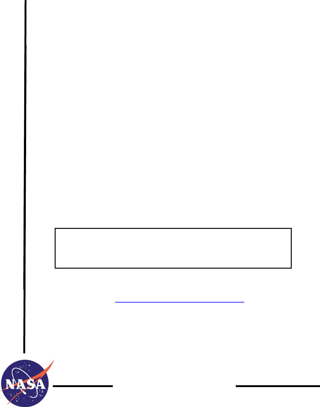
tracking system, or dedicated ground terminal. Figure 1-1 depicts the RF links between the
Spacecraft and its various interfaces.
1.3.2 Link Calculations
The RF link calculations contained in Appendix A for the Spacecraft modes of operation are
included only as supporting data and do not constitute a formal part of the RF ICD agreement.
The Earth-coverage antenna patterns and downlink spectrum provided in Appendix B and
Appendix C, respectively, are included for information purposes and are also not part of this RF
ICD agreement.
1.3.3 Other RF Interfaces
The RF interfaces between the JPSS-1 Spacecraft and the Space Network (SN), the JPSS-1
Spacecraft and the S-Band Ground Stations, and the JPSS-1 Spacecraft and the Ka-Band Ground
Stations are included in separate RF ICDs. This ICD provides the definition of the HRD links
between the JPSS-1 Spacecraft and the X-Band Direct Broadcast Users.
JPSS-1 HRD DBS RF ICD 472-00165
Effective Date: February 5, 2015
Revision: A
2
Figure 1-1. Spacecraft Communications Links
JPSS-1 HRD DBS RF ICD 472-00165
Effective Date: February 5, 2015
Revision: A
3
2. Documents
2.1 Applicable Documents
The following documents are applicable to the JPSS-1 Spacecraft.
GSFC 472-00009 JPSS-1 Satellite Requirements Specification
National Telecommunications and Information Administration (NTIA), Manual of
Regulations and Procedures for Federal Radio Frequency Management (Redbook)
2.2 Reference Documents
The following documents are reference documents applicable to the RF interface being
controlled. These documents do not form a part of this ICD and are not controlled by their
reference herein.
CCSDS 131.0-B-2 Consultative Committee for Space Data Systems (CCSDS)
Recommendations for TM Synchronization and Channel Coding
CCSDS 133.0-B-1 Consultative Committee for Space Data Systems (CCSDS)
Recommendations for Advanced Orbiting Systems – Networks and
Data Links: Architectural Specification
CCSDS 732.0-B-2 Consultative Committee for Space Data Systems (CCSDS)
Recommendations for Advanced Orbiting Systems (AOS) Space Data
Link Protocol
GSFC 429-01-02-19 IRD for NPP Mission System to Direct Broadcast Users Interface
ITU-R SA 1157 Protection Criteria for Deep-Space Research
GSFC 472-00163 JPSS-1 Mission Data Format Interface Control Document (ICD)
2.3 Other Related Documents
The following documents are listed for the convenience of the user. These documents do not
form a part of this ICD and are not controlled by their reference herein.
INTENTIONALLY REMOVED
JPSS-1 HRD DBS RF ICD 472-00165
Effective Date: February 5, 2015
Revision: A
4
3. Communications Interface Requirements
3.1 HRD Link Overview
3.1.1 General
The Spacecraft will use an Earth-coverage pattern antenna to provide downlink for Direct
Broadcast Users. It provides real-time mission data (which includes instrument science data,
instrument engineering data, and instrument telemetry data), and real-time Spacecraft
housekeeping data. The data rate is 15 Mbps at a nominal downlink frequency of 7812 MHz. In
normal operations broadcast data will operate continuously providing real-time data to the Direct
Broadcast Users.
3.1.2 Interface RF Links
The required RF communication links are as follows:
a. Mission data from Spacecraft-to-Direct Broadcast Users
b. Pseudo Random Bit Stream (PRBS) for Bit Error Rate (BER) measurements
3.2 Interface Functional Requirements
3.2.1 General
Paragraphs 3.2.2 to 3.2.5 describe the X-Band interface functional requirements that exist
between the Spacecraft and the Direct Broadcast Users.
3.2.2 Overview
The HRD system hardware onboard the Spacecraft consists of two transmitters, one transfer
switch, and one shaped reflector antenna. The antenna is designed to give Earth-coverage
radiation pattern. Antenna patterns are shown in Appendix B for reference. The system is
designed to always be on, with the ability to be turned off indefinitely. Figure 4-6 shows the
architecture for the HRD system and the interface to the Mission Data Formatter (MDF). The
Direct Broadcast User Terminal demodulates and decodes the RF received from the Spacecraft
communication subsystem. The Spacecraft to Earth station link distance ranges from 2835 Km
at a ground station elevation angle of 5°, to 824 Km at a ground station elevation angle of 90°.
Direct Broadcast Station support is dependent on favorable radio line-of-sight conditions when
Direct Broadcast Station antenna elevation angle is greater than 5° (above the local horizon).
3.2.3 Mission Data
Transmission of real-time payload data from the Spacecraft to Direct Broadcast Users of HRD
occurs at 15 Mbps. Mission data will be formatted in accordance with Spacecraft requirements
outlined in paragraph 4.3. The 15 Mbps is the Channel Access Data Unit (CADU) bit rate,
measured after Reed-Solomon coding and pre-pending the Attached Sync Marker. After rate 1/2
convolutional coding is applied, the in-phase (I)- and quadrature-phase (Q)-channels are each
Quadrature Phase Shift Key (QPSK) modulated with 15 Msps (30 Msps total). Data from the
JPSS-1 HRD DBS RF ICD 472-00165
Effective Date: February 5, 2015
Revision: A
5
HRD is selectable by Application Identification (APID) via table load. In all cases, fill frames
are added in order to maintain the 15 Mbps downlink rate.
3.2.4 Pseudo-Random Bit Stream (PRBS)
The satellite will generate pseudo-random bit stream test data as a test mode used for the purpose
of BER checking, as required. It is not a normal X-Band spacecraft operation. The satellite shall
reset upon command back to the default configuration from the pseudo-random output.
NOTE:
The link analysis for the PRBS is not shown since the Mission Data link analysis is worst case.
3.2.5 Doppler Tracking and Ranging
The Direct Broadcast Stations must be able to handle a maximum Doppler shift of ± 171.0 kHz
at an elevation angle of 5°, and a Doppler shift rate of 1.55 kHz/sec at an elevation angle of 90°.
This link does not provide a ranging capability.
3.3 Communications Performance Characteristics
3.3.1 General
RF link performance requirements for the communications functional capability described in
paragraph 3.2 are defined in this section. Direct Broadcast Station communications performance
requirements are based on the presumption that the Spacecraft and Direct Broadcast Station each
perform in accordance with the system performance parameters defined in Section 4.
3.3.2 Mission Data Channel BER
The maximum HRD downlink information BER for the mission data channel will be 1.83x10
-3
,
referenced to the input of a Reed Solomon (RS) Decoder on the ground. With RS decoding at
the Direct Broadcast terminal, the effective output mission data BER will be 10
-8
. The HRD
Interface Requirements Document (IRD) requires an E
b
/N
o
of 4.4 dB, which is more stringent
than the 10
-8
BER requirement. Therefore the link analysis is performed using the E
b
/N
o
requirement of 4.4 dB.
3.3.3 PRBS Test Channel BER
The maximum HRD downlink information BER for the PRBS test channel will be 1x10
-4
,
referenced to the output of the Viterbi decoder on the ground per the HRD IRD. Actual
performance will be better than 10
-5
based on the E
b
/N
o
requirement of 4.4 dB.
3.4 Spacecraft/Direct Broadcast Station Communication Link (X-Band Downlink
Modes)
The Spacecraft X-Band downlink modes are shown in Table 3-1.

JPSS-1 HRD DBS RF ICD 472-00165
Effective Date: February 5, 2015
Revision: A
6
Table 3-1. Spacecraft HRD Communication Modes
Service
Data Mode
Rate
(Mbps)
Antenna
(Polarization)
Modulation
I:Q Power
Ratio
Direct
Broadcast
Users
HRD
(mission data)
15
Earth-coverage
antenna
(RHCP)
QPSK
1:1
Direct
Broadcast
Users
PRBS
15
Earth-coverage
antenna
(RHCP)
QPSK
1:1
JPSS-1 HRD DBS RF ICD 472-00165
Effective Date: February 5, 2015
Revision: A
7
4. HRD Link Interface Characteristics
4.1 Purpose
This section specifies the functional design of the RF HRD link. Pertinent Spacecraft and Direct
Broadcast Station communications signal designs and system performance requirements are also
specified.
4.2 Link Functional Designs: Spacecraft-to-Direct Broadcast Stations HRD Downlink
4.2.1 General
The HRD transmitter will be used to transmit the data for this link. Baseband characteristics will
be in accordance with Table 4-1. The Earth-coverage antenna provides 15 Mbps data to the
Direct Broadcast Users. The HRD system is designed to transmit data at all times, however, it
can be turned off indefinitely if the need arises.
4.2.2 Functional Description
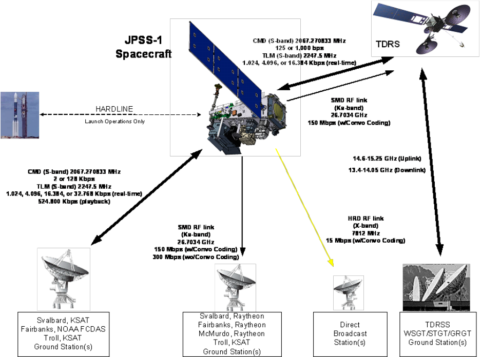
The functional interface of the Mission Data link will be as shown in Figure 4-1, and the
functional interface of the PRBS test bit stream link will be as shown in Figure 4-2.
a. Spacecraft mission data or PRBS data are sent from the MDF board within the Command
and Data Processor (CDP) to the HRD transmitters. The signal from the CDP is Low
Voltage Differential Signal (LVDS) in a Non-return to Zero Level (NRZ-L) format.
b. The data are then converted from NRZ-L to Non-return to Zero Mark (NRZ-M) format
and is then convolutionally encoded.
c. The convolutional encoder outputs are split with G1 on the I-channel and G2 (inverted)
on the Q-channel. The I-channel and Q-channel data is QPSK modulated onto the X-
Band carrier with an I/Q-channel power ratio of 1:1 as shown in Figure 4-1 and Figure 4-
2. The X-Band carrier is derived from a Temperature Compensated Crystal Oscillator
(TCXO).
d. These data streams QPSK modulate onto a 7812 MHz carrier. The resulting Transmitter
RF output is amplified to 7 watts minimum, over full specified unit temperature range, 8
watts minimum at maximum flight allowable temperature range. The link uses the Earth-
coverage antenna to transmit to Direct Broadcast Users.
JPSS-1 HRD DBS RF ICD 472-00165
Effective Date: February 5, 2015
Revision: A
8
Figure 4-1. Spacecraft-to-Direct Broadcast Station Downlink Configuration (Mission
Data)
Figure 4-2. Spacecraft-to-Direct Broadcast Station Downlink Configuration (PRBS Mode)

JPSS-1 HRD DBS RF ICD 472-00165
Effective Date: February 5, 2015
Revision: A
9
4.2.2.1 Data Formatting
Data formatting for Mission Data is as follows (see Figure 4-1):
a. CCSDS format into coded Advanced Orbiting Systems (AOS) Transfer Frames (TF),
(formerly referred to as Coded Virtual Channel Data Units (CVCDU’s)) with Reed
Solomon (RS) (255,223), I=4
b. Randomize coded AOS transfer frames (see Section 4.3.4)
c. CCSDS format into Channel Access Data Units (CADU’s) by adding sync (see Section
4.3.4)
d. Differential encode
e. Convolutional encode (as described in paragraph 4.3.6)—the G1 output will be routed to
the I channel, and the G2 (inverted) output will be routed to the Q channel of the HRD
transmitter.
Data formatting for PRBS mode is as follows (see Figure 4-2):
a. All zeroes input
b. Randomize the input by using the following bit transition generation function (refer to
CCSDS 131.0-B-2 Recommendations for TM Synchronization and Channel Coding,
Section 9):
h(x) = x
8
+ x
7
+ x
5
+ x
3
+1
c. Differential encode
d. Convolutional encode (as described in paragraph 4.3.6)—the G1 output will be routed to
the I channel, and the G2 (inverted) output will be routed to the Q channel of the HRD
transmitter.
When operating in the PRBS mode, the CADU sync pattern is disabled. See also Figure 4-6.
Details of data formatting are further covered in the JPSS-1 Mission Data Format ICD.
4.2.2.2 Direct Broadcast User Ground Station Functionality
At the Direct Broadcast Users Receive Ground Station, the input signal from the receive antenna
is down converted before being input to the QPSK receiver/demodulator. The QPSK
receiver/demodulator demodulates the down converted signal into separate I and Q channel data
streams with NRZ-M format. Following QPSK demodulation, the bit synchronizers recover
symbol clock, the data are Viterbi decoded, and converted to NRZ-L format. After conversion to
NRZ-L the data will be de-randomized. Table 4-1 contains minimum performance requirements
for the Direct Broadcast capability of the spacecraft and the Users Ground Stations.
Table 4-1. HRD Downlink Baseband and RF Signal Parameters vs Capability
Parameter
Requirement
Capability
Comply
Transmit Center
Frequency
7812 0.03 MHz
7812 0.03MHz
Yes
Data Rate
15,000,000 bps +/- 6 Kbps
15,000,000 bps +/- 6
Kbps
Yes
Polarization
RHCP
RHCP
Yes

JPSS-1 HRD DBS RF ICD 472-00165
Effective Date: February 5, 2015
Revision: A
10
Axial Ratio
Ground
Elevation
Angle (deg)
Angle from
Spacecraft
Antenna
Boresight (deg)
Axial
Ratio
(dB)
Angle from
Spacecraft
Antenna
Boresight (deg)
Axial
Ratio
(dB)
NA
5
40
70
90
61.9
42.7
17.6
0
None
61.9
42.7
17.6
0
6.0
Coverage
62
62 (1)
Yes
Minimum EIRP (dBm)
Ground
Elevation
Angle (deg)
Angle from
Spacecraft
Antenna
Boresight (deg)
EIRP
(dBm)
Angle from
Spacecraft
Antenna
Boresight (deg)
EIRP
(dBm)
5
40
70
90
61.9 0.1
42.7 0.1
17.6 0.1
0 0.1
42.8
33.6
30.8
30.3
61.9 0.1
42.7 0.1
17.6 0.1
0 0.1
43.1
35.2
33.6
31.2
Yes
Data Modulation
QPSK
Compliance
Yes
Data Format, Modulator
Output
NRZ-M output
Compliance
Yes
Assigned Bandwidth (-20
dB)
30 MHz
30 MHz
Yes
Gain Slope over f
c
15
MHz
0.2 dB/MHz
Angle from
Spacecraft
Antenna
Boresight (deg)
Gain
Slope
61.9
43.6
17.9
0
0.001
0.001
0.001
0.001
Yes
Gain Flatness over f
c
15MHz
2.0 dB p-p
2.0 dB p-p
Yes
Phase Non-linearity over f
c
15 MHz
6 degrees p-p
6 degrees p-p
Yes
I/Q Power Ratio (Nominal)
1:1
1:1
Yes
I/Q Power Ratio Tolerance
0. 5 dB
0. 5 dB
Yes
QPSK Phase Imbalance
4.5
4.5
Yes
QPSK Gain Imbalance
1 dB p-p
1 dB p-p
Yes
Data Asymmetry
3%
3%
Yes
Data Bit Jitter
1%
1%
Yes
Phase Noise (Offset from
Carrier) 100 Hz – 40 MHz
Spurious Phase
Modulation
2.0 degrees RMS
2.0 degrees RMS
2.0 degrees RMS
2.0 degrees RMS
Yes
AM/PM
10°/dB
<10°/dB
Yes
I/Q Data Skew
< 5% of bit period
< 5% of bit period
Yes
Operational Duty Cycle,
Science Mode
100%
100%
Yes
Service Interruption
HRD shall have the ability to be turned ON
or OFF
HRD can be commanded
ON or OFF
Yes
Frequency Stability
Over all conditions
1x10
-5
1x10
-5
Yes
HRD System BER
1x10
-8
(link margin 1 dB)
1x10
-8
Yes
Untracked Spurious PM
(100 Hz to 40 MHz)
2
2
Yes
Carrier Suppression
≤ -30 dBc
-30 dBc
Yes
Spurious Emissions (out-
of-band)
≤ -60 dBc
-60 dBc
Yes

JPSS-1 HRD DBS RF ICD 472-00165
Effective Date: February 5, 2015
Revision: A
11
4.3 Baseband Signal Characteristics
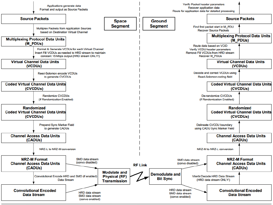
4.3.1 General
This paragraph provides a description of the baseband signal characteristics of the HRD
downlink signal to the Direct Broadcast Users. The formatting process is illustrated in Figure 4-
7.
4.3.2 Mission Data Baseband Signal Parameter
The Spacecraft HRD downlink baseband signal parameters for the mission data are contained in
Table 4-1, along with the modulation and RF signal parameters.
4.3.3 HRD Formatter
The MDF within the CDP shall provide a HRD Formatter function that allows CCSDS CADUs
to be generated from CCSDS AOS transfer frames provided by the CDP flight software (FSW).
The HRD Formatter shall apply Reed-Solomon coding to create Coded AOS transfer frames.
The Reed Solomon code used shall be standard CCSDS 255,223 with interleave depth 4 as
defined in CCSDS 131.0-B-2, Section 4. The addition of Reed-Solomon coding to the incoming
AOS transfer frames was previously defined as CCSDS Grade 2 telemetry service (historically
defined in CCSDS 701.0-B-3, Paragraphs 2.3.3 and 2.4.1.2.f) but this terminology is no longer
used in the recommendations. A block diagram of the HRD Formatter and transmitter is shown
in Figure 4-6. Fill frames with Virtual Channel 63 are added as necessary at the AOS transfer
frame level in order to maintain a constant 15 Mbps formatted downlink rate as shown in the
diagram. In order to perform BER tests, an all 0’s input may be switched into the system prior to
the randomizer as shown in Figure 4-6. Additionally, the PRN stream has the CADU Sync
Marker turned off.
Ground Station Pointing
Loss
1 dB
1 dB
Yes
Ground Station
Implementation Loss
2.5 dB
2.5 dB
Yes
Ground Station Multipath
Loss at 5 Elevation angle
0.2 dB
0.2 dB
Yes
Ground Station G/T (dB/K)
3 meter antenna
Reference: IRD for NPP
Mission System to Direct
Broadcast Users
Interface
Ground Elevation
G/T (dB/K)
(2)
Ground
Elevation
G/T
(dB/K) (2)
Yes
5
40
70
90
22.7
23.59
23.65
23.66
5
40
70
90
22.7
23.59
23.65
23.66
NOTE
1. Allows for +/-0.3 degree pointing uncertainty
2. The link availability is dependent upon actual location of the User Terminal. Reference the Link Analysis in
Appendix A.
JPSS-1 HRD DBS RF ICD 472-00165
Effective Date: February 5, 2015
Revision: A
12
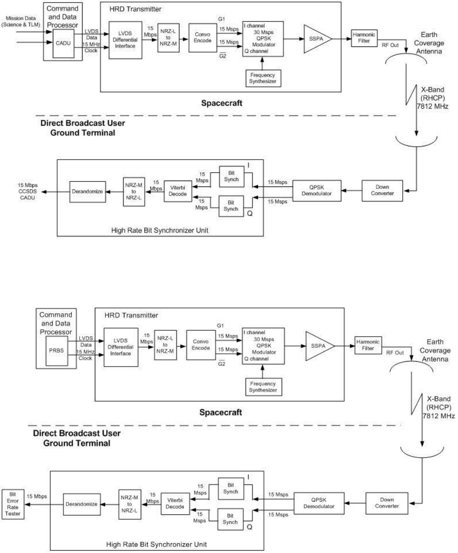
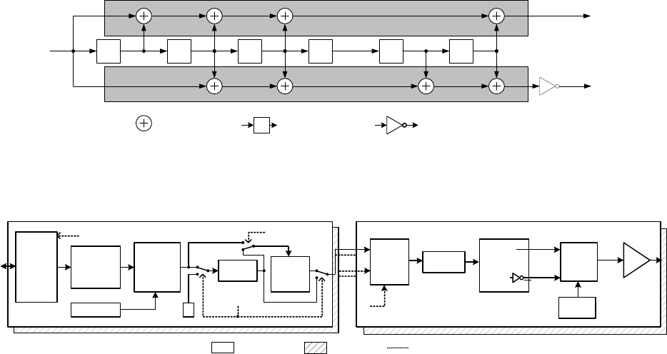
4.3.4 HRD Randomizer
The HRD Formatter shall provide a function to randomize telemetry data contained in AOS
transfer frames. The randomization process shall be Enable/Disable selectable by command.
The data shall be randomized in compliance with CCSDS 131.0-B-2, Section 9, when the HRD
data randomizer is enabled. The HRD Randomizer configuration is illustrated in Figure 4-3. The
Logic for the HRD data randomizer is shown in Figure 4-4. The data shall bypass this process
when the HRD data randomizer is disabled. The 32-bit synchronization marker is added to each
Data Unit in order to complete the CADU format.
Coded AOS TF
from Data Stream
Pseudo-Random
Sequence Generator
En/Ds Command
Sync Pattern
Generator
CADU
Process
Data Output
(CCSDS CADU)
Figure 4-3. HRD Randomizer Configuration
X
8
X
7
X
6
X
5
X
4
X
3
X
2
X
1
Initialize to an "all ones" state for each Coded AOS TF
during the period when the Sync Pattern is selected.
=Modulo-2 adder
(Exclusive-OR)
=Single Bit Delay
Pseudo-random
sequence
DATA OUT
(Randomized Coded AOS TF)
DATA IN
(Coded AOS TF)
Figure 4-4. HRD Randomizer Logic Diagram
4.3.5 Data and Symbol Signal Formats
After randomization and insertion of the frame synchronization marker, the signal is serially
converted from NRZ-L to NRZ-M.
JPSS-1 HRD DBS RF ICD 472-00165
Effective Date: February 5, 2015
Revision: A
13
4.3.6 Convolutional Coding
The Spacecraft will encode the HRD stream with a rate ½, constraint length 7 convolutional
coding as defined in CCSDS 131.0-B-2, Section 3. Figure 4-5 shows the encoder block diagram.
The convolutional encoder outputs are routed with G1 to the I channel and G2 (inverted) to the Q
channel of the modulator.
D
=Modulo-2 adder
(Exclusive-OR)
= Single Bit Delay
D D D D D
G2
= Inverter
Outputs from the
convolutional encoder
map to the I and Q
inputs of the QPSK
Modulator
INPUT DATA
STREAM
G1
D
Q
I
Figure 4-5. CCSDS Recommendation for Telemetry Channel Coding
MDF-2
HRDTx-2
MDF-1
Input Buffer
(AOS TFs
From
CDP FSW)
Extract AOS TF
and perform
AOS TF
Header Check
Generate
CCSDS
Coded AOS TFs
(add RS Coding)
PRN Gen/
Randomizer
Randomize
Enable/Disable Cmd
Generate
CCSDS
CADUs
(ASM)
LVDS
Fill (VC63)
Clear Cmd
0
Test Mode
Enable/Disable Cmd
HRDTx-1
Input MUX
A/B input select
NRZ-L to
NRZ-M
Rate 1/2, K=7
Convo Encode
QPSK
Modulater
X-Band
Synth
SSPA
Input A
Q
I
G1
G2
G2
G1
Input B
COLD SPARE
REDUNDANT
CONNECTION
PRIMARY
UNIT
Figure 4-6. HRD Formatter/Transmitter Block Diagram
JPSS-1 HRD DBS RF ICD 472-00165
Effective Date: February 5, 2015
Revision: A
14
Figure 4-7. CCSDS HRD Formatting
4.4 RF Signal Characteristics
4.4.1 General
For the Spacecraft-to-Direct Broadcast Users HRD 15 Mbps downlink, balanced QPSK
modulation (channel power ratio of 1:1) is used.
4.4.2 Signal Characteristics
The signal characteristics of the HRD downlink are in accordance with Table 4-1. QPSK
modulation is employed. The X-Band carrier is modulated by the I and Q baseband signals. The
HRD downlink uses an Earth-coverage antenna on the Spacecraft.
4.4.2.1 DSN Protection
Deep Space Network (DSN) interference criteria of, –255.1 dBW/m
2
Hz from 8400 to 8450
MHz, is met by filtering the HRD transmitter appropriately in this band.
Table 4-2 shows the DSN power Flux Density Analysis.

JPSS-1 HRD DBS RF ICD 472-00165
Effective Date: February 5, 2015
Revision: A
15
Table 4-2. DSN Power Flux Density Analysis
Parameter
Power
Units
Reference
HRDTx Po
14.0
watts
Max Spec Power
Power in dBW
11.46
dBW
Passive Loss
-2.0
dB
Lowest case loss
Ant Gain
(worst case peak)
9.5
dBi
Worst case antenna gain
(SC not nadir pointed)
EIRP
18.96
dBW
(sum of above)
RF vs. unmodulated
-71.8
dB
(Sin X)/X loss
-41.9
dB
Peak 8400 to 8450 MHz
Filter Loss
-56
dB
Tx Filter at 39th sideband
Spectral re-growth
(estimate)
10
dB
amplifier in some compression
Spreading factor
-129.3
dB
824 Km distance
(S/C directly over DSN)
Total
-270.04
dBW/m
2
per Hz
Requirement
-255.1
dBW/m
2
per Hz
SA 1157 8400 to 8450 MHz
Margin
14.94
dB
Worst Case
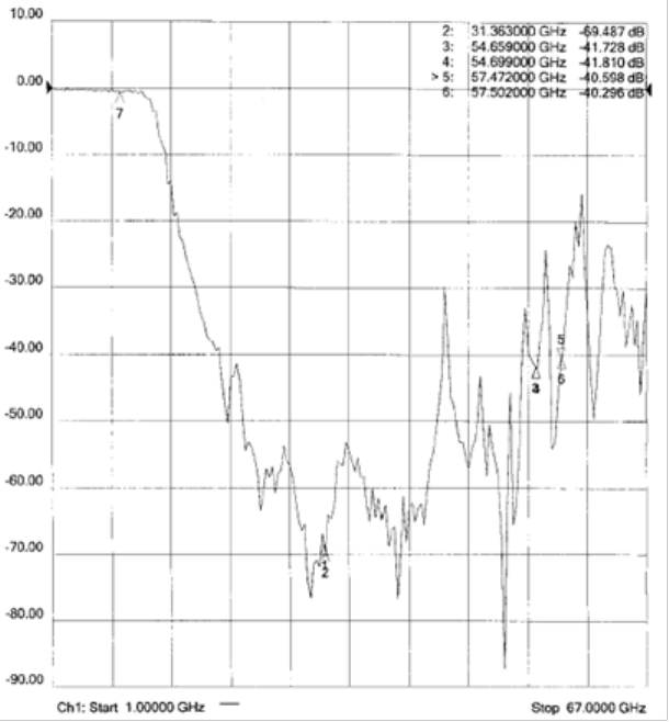
4.4.2.2 High Frequency Harmonic Protection
A post HRD transmitter output X-Band Bandpass filter will be employed to best comply with the
protection of payload electronics. The passband and stopband filtering characteristics are shown
in Figure 4-8.
JPSS-1 HRD DBS RF ICD 472-00165
Effective Date: February 5, 2015
Revision: A
16
Figure 4-8. HRD Harmonic Filter, Passband and Stopband response
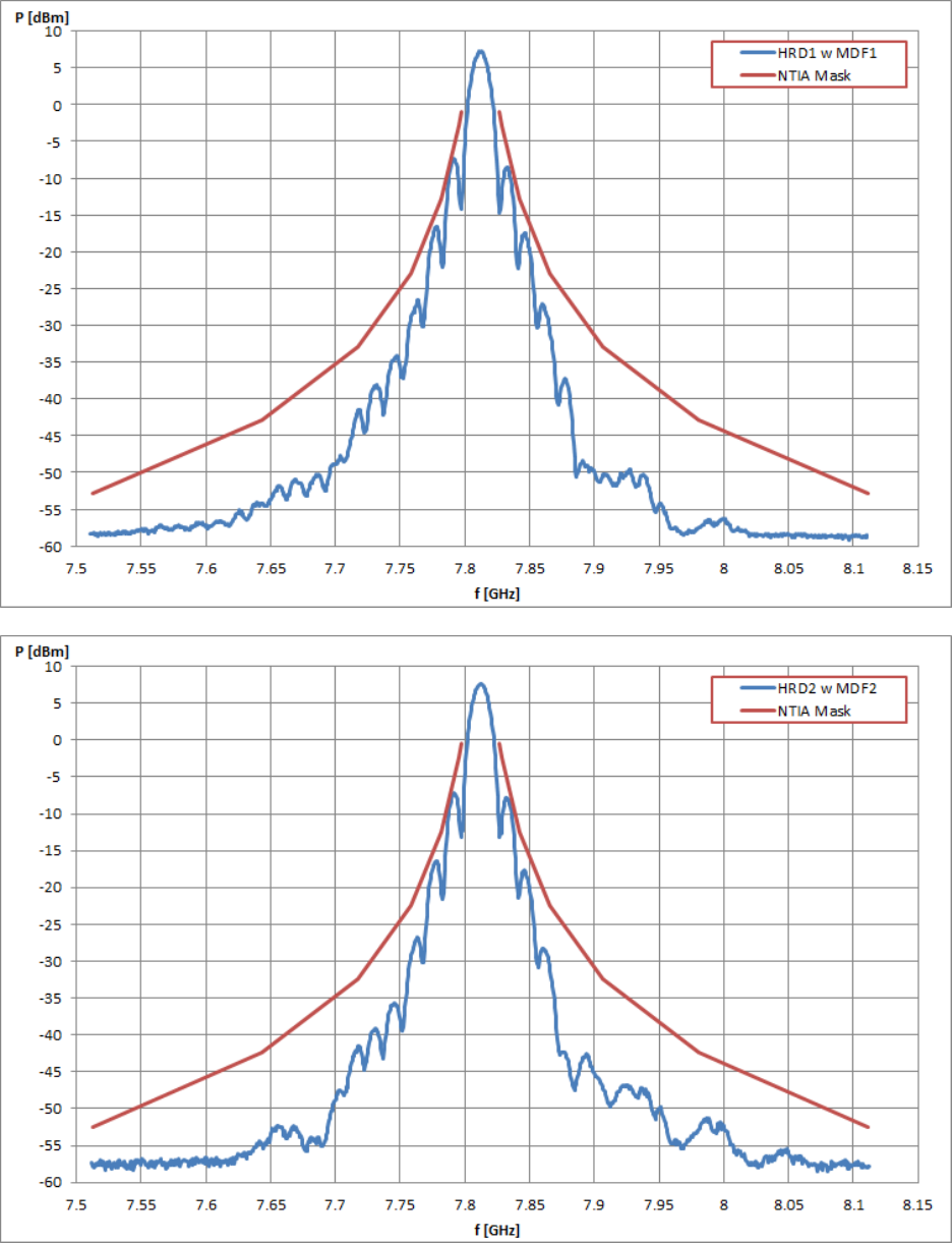
4.4.2.3 NTIA Bandwidth
The filtering of the HRD downlink will be within the NTIA bandwidth mask as shown in
Figure 4-9.
JPSS-1 HRD DBS RF ICD 472-00165
Effective Date: February 5, 2015
Revision: A
17
Figure 4-9. NTIA Bandwidth Requirement
JPSS-1 HRD DBS RF ICD 472-00165
Effective Date: February 5, 2015
Revision: A
18
4.4.2.4 Filter Characteristics
A pre-final amplifier filter is employed to meet the requirement of 4.4.2.1 and 4.4.2.2. The filter
characteristic is shown in Figure 4-9. The spectral output is shown in Appendix C.
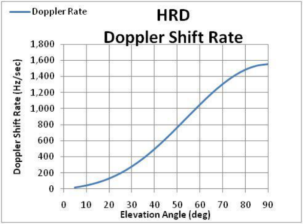
4.4.2.5 Doppler Shift
The Spacecraft will be traveling at a velocity of ~7.44 Km/sec at an altitude of 824 Km, this
results in a maximum Doppler shift of ±171.0 kHz at an elevation angle of 5°. Figure 4-10
shows the Doppler shift rate as the Spacecraft travels over the different elevation angles. The
max rate of change of 1.55 kHz/sec occurs at an elevation angle of 90°.
Figure 4-10. Doppler Shift Rate vs Elevation Angle
4.4.2.6 Spurious Emissions
All out-of-band spurious emissions will be less than –60 dBc.
4.5 Ground Interface testing
4.5.1 HRD Compatibility Test
The JPSS-1 Spacecraft will be made available to perform HRD compatibility testing for the
purpose of verifying compatibility with the specified HRD ground station. A hard-line RF
output from the transmitter and an air link path will be available for this compatibility testing.
4.5.2 End-to-End Test
For End-to-End (ETE) testing during JPSS-1 Compatibility Tests (JCTs), a hardline RF output
with the HRD signal will be made available for use with the ground receiver and processor
located in the Satellite factory clean room. The RF signal will have the characteristics described
above in sections 4.1 through 4.4.
JPSS-1 HRD DBS RF ICD 472-00165
Effective Date: February 5, 2015
Revision: A
19
4.6 HRD Scheduling
Mission Support Data (MSD) regarding JPSS-1 scheduling, ephemeris information, predicted
outages, and other user messages will be stored on the JPSS Field Terminal Support (FTS) Web-
portal. Direct Broadcast Users may retrieve the mission support data from the FTS Web-portal
via the internet. The FTS Web-portal access will be granted to the Direct Broadcast User upon
registration with the JPSS Program.
JPSS-1 HRD DBS RF ICD 472-00165
Effective Date: February 5, 2015
Revision: A
20
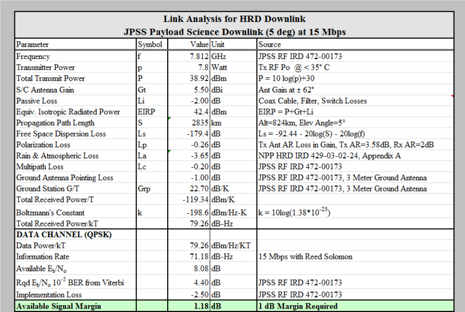
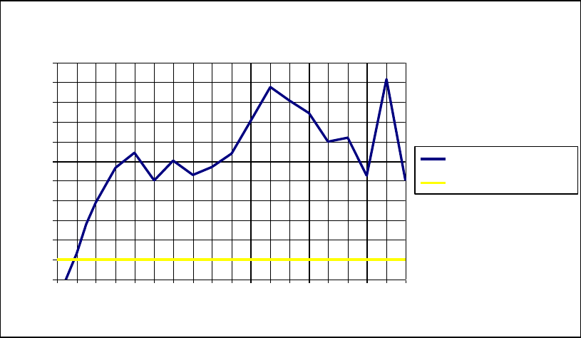
Appendix A RF Link Calculations
Figure A-1 summarizes the worst case HRD link margin with a 5
o
elevation angle. Figure A-2
has been included to show the link margins over various elevation angles.
Figure A-1. Link Analysis at 5° Elevation Angle
JPSS-1 HRD DBS RF ICD 472-00165
Effective Date: February 5, 2015
Revision: A
21
HRD Margin vs. Elevation Angle
0
1
2
3
4
5
6
7
8
9
10
11
0 5 10 15 20 25 30 35 40 45 50 55 60 65 70 75 80 85 90
Elevation Angle (Degrees)
Margin (dB)
HRD Link Margin
1 dB Margin
Figure A-2. Typical Link Analysis vs User Terminal Elevation Angle
JPSS-1 HRD DBS RF ICD 472-00165
Effective Date: February 5, 2015
Revision: A
22
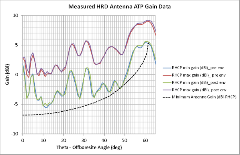
Appendix B Earth Coverage Antenna Patterns
Figure B-1 shows the Earth Coverage HRD antenna patterns as a function of the offpoint angle.
Contained within these plots is the RHCP antenna gain and the minimum antenna gain. As
shown in this figure the Earth Coverage antenna maintains the necessary link margin over all
angles.
Figure B-1. Single Sided Antenna Pattern Requirement as a Function of Offpoint Angle
JPSS-1 HRD DBS RF ICD 472-00165
Effective Date: February 5, 2015
Revision: A
23
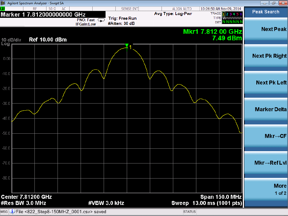
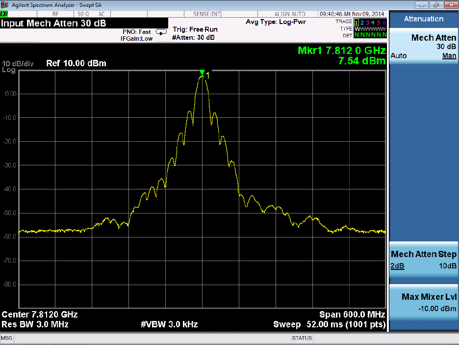
Appendix C HRD Spectrum
JPSS-1 HRD DBS RF ICD 472-00165
Effective Date: February 5, 2015
Revision: A
24
Figure C-1. Spectral Plots
JPSS-1 HRD DBS RF ICD 472-00165
Effective Date: February 5, 2015
Revision: A
25
Appendix D Acronyms and Abbreviations
AM
Amplitude Modulation
AOS
Advanced Orbiting Systems
APID
Application Identification
BATC
Ball Aerospace and Technology Corporation
BER
Bit Error Rate
bps
bits per seconds
C
Celsius
CADU
Channel Access Data Unit
CCB
Change Control Board
CCSDS
Consultative Committee for Space Data Systems
CDP
Command and Data Processor
CMD
Command
CVCDU
Coded Virtual Channel Data Unit
dB
Decibel
dBc
Decibel/carrier
dBi
Decibel Isotropic
dB/K
Decibel/Kelvin
dBm
Decibel/miliwatt
DBS
Direct Broadcast Stations
dBW
Decibel/Watt
deg
degrees
Ds
Disable
DSN
Deep Space Network
EIRP
Effective Isotropic Radiated Power
En
Enable
ETE
End-to-End
FSW
Flight Software
GHz
Giga Hertz
GSFC
Goddard Space Flight Center
G/T
Gain-to-Noise Temperature Ratio
HRD
High Rate Data
HRDTx
High Rate Data Transmitter
Hz
Hertz
I
In-phase
ICD
Interface Control Document
IRD
Interface Requirements Document
JCT
JPSS Compatibility Tests
JPSS-1
Joint Polar Satellite System-1
K
Kelvin
Kbps
Kilo bits per second
Km
Kilometer
LVDS
Low Voltage Differential Signal
JPSS-1 HRD DBS RF ICD 472-00165
Effective Date: February 5, 2015
Revision: A
26
Mbps
Mega bits per second
MDF
Mission Data Formatter
MHz
Mega Hertz
MSDS
Mission Support Data Server
Msps
Mega symbols per second
NASA
National Aeronautics and Space Administration
NPOES
National Polar-Orbiting Operational Environmental Satellite System
NPP
NPOESS Preparatory Project
NRZ
Non Return to Zero
NRZ-L
Non Return to Zero-Level
NRZ-M
Non Return to Zero-Mark
NTIA
National Telecommunications and Information Administration
PCM
Pulse Code Modulation
PM
Phase Modulation
PO
Program Office
p-p
peak-peak
PRBS
Pseudo-Random Bit Stream
PRN
Pseudo-Random Noise
Q
Quadrature
QPSK
Quadrature Phase Shift Key
RF
Radio Frequency
RFICD
Radio Frequency Interface Control Document
RHCP
Right Hand Circular Polarization
RMS
Root Mean Square
RS
Reed Solomon
S/C
Spacecraft
sec
second
SER
System Engineering Report
SN
Space Network
SNUG
Space Network Users’ Guide
SSPA
Solid State Power Amplifier
synch
synchronizer
TBD
To Be Determined
TBR
To Be Reviewed
TCXO
Temperature Compensated Crystal Oscillator
TDRS
Tracking and Data Relay Satellite
TDRSS
Tracking and Data Relay Satellite System
TF
Transfer Frame
TLM
Telemetry
URL
Uniform Resource Locator
VCDU
Virtual Channel Data Unit
