
HT32 MCU UART Application Note
AN0609EN V1.00 1 / 23 June 23, 2022
HT32 MCU UART Application Note
D/N: AN0609EN
Introduction
The Universal Asynchronous Receiver/Transmitter – UART is a widely used serial transmission
interface that provides flexible asynchronous full-duplex data transmission.
The “Module_UART” application code provided in this application note uses TX/RX interrupts
with software ring buffers to implement simple UART transmit/receive functions through APIs,
whose related functions are described below. This will simplify the entire data transmission process
and allow users to quickly understand and implement UART communication applications.
Transmit/receive functions: byte read, byte write, buffer read, buffer write, etc.
Status functions: obtain the buffer length, TX status, etc.
This document will first introduce the UART communication protocol, which will help users to
better understand the UART communication from principle to application. This is followed by the
download and preparation of the resources required for the application code, including the firmware
library, application code download, file and directory configuration as well as an introduction to
the terminal software tool used in the application note. In the Functional Description chapter, the
application code directory structure, parameter settings and API description will be introduced. The
API usage will be described using the “Module_UART” application code and the Flash/RAM
resource consumption required for the APIs will also be listed. The Instructions for Use chapter
will guide the user through the steps of environmental preparation, compilation and test to confirm
that the application code will work properly. It will then provide instructions explaining how to
integrate the APIs into the user’s projects and finally provide a reference for modifications and
common problems that may be encountered.
Abbreviations used:
UART: Universal Asynchronous Receiver/Transmitter
API: Application Programming Interface
LSB: Least Significant Bit
MSB: Most Significant Bit
PC: Personal Computer
SK: Starter Kit, HT32 development board
IDE: Integrated Development Environment

HT32 MCU UART Application Note
AN0609EN V1.00 2 / 23 June 23, 2022
UART Communication Protocol
The UART is a serial communication type of interface that implements parallel-to-serial data
conversion at its transmitter and then communicates serially with a similar receiver. The receiver
then performs a serial-to-parallel data conversion after data reception. Figure 1 shows a schematic
diagram of serial communication showing how the data is transferred in a bitwise order. Therefore
for bidirectional communication between transmitter and receiver, only two wires, TX and RX, are
required to transfer data serially between each other. TX is the pin on which the UART transmits
the serial data and is connected to the RX pin of the receiver. Therefore the transmitter and receiver
devices need to cross-connect their TX and RX pins to perform UART two-way communication,
as shown in Figure 2.
Figure 1. Serial Communication Diagram
Figure 2. UART Circuit Diagram
During the UART serial communication, data transmission is asynchronous. This means that there is
no clock or other synchronisation signal between the transmitter and receiver. Here a baud rate is used,
which is the serial data transmitting/receiving speed and which is set by both sides in advance of data
transfers. In addition, special bits such as start and stop bits are added to the beginning and end of the
data packet to form a complete UART data packet. Figure 3 shows the UART data packet structure
while Figure 4 shows a UART 8-bit data packet without a parity bit.
Figure 3. UART Data Packet Structure
Figure 4. UART 8-bit Data Packet Format
HT32 MCU UART Application Note
AN0609EN V1.00 3 / 23 June 23, 2022
Each part of the UART data packet is introduced in order below.
Start Bit: This indicates the start of a data packet. The UART TX pin usually remains at a high
logic level before transmission starts. If data transmission starts, the UART transmitter will pull
the TX pin from high to low, i.e., from 1 to 0, and then hold it there for one clock cycle. The UART
receiver will start reading data when a high to low transition has been detected on the RX pin.
Data: This is the actual data transferred, with a data length of 7, 8 or 9 bits. The data is usually
transferred with the LSB first.
Parity Bit: The number of logic “1” in the data is used to determine whether any data has changed
during transmission. For even parity, the total number of logic “1” in the data should be an even
number, conversely, the total number of logic “1” in the data should be an odd number for odd
parity.
Stop Bit: This indicates the end of a data packet, where the UART transmitter will pull the TX
pin from low to high, i.e., from 0 to 1, and then hold it there for a 1 or 2-bit time period.
As mentioned before, since there is no clock signal in the UART circuit, the same serial data
transmitting/receiving speed, which is known as the baud rate, must be defined between the
transmitter and receiver to implement error-free transmission. The baud rate is defined by the
number of bits transferred per second, in bps (bit per second). Some standard and commonly used
baud rates are 4800bps, 9600bps, 19200bps, 115200bps, etc. The corresponding time required for
transferring a single data bit is shown below.
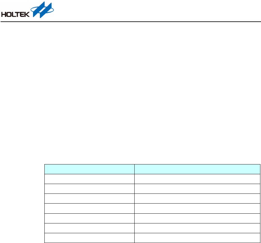
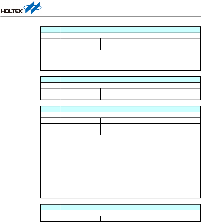
Baud Rate
1-Bit Transmission Time
4800bps
208.33µs
9600bps
104.16µs
19200bps
52.08µs
115200bps
8.68µs
Table 1. Baud Rate vs. 1-Bit Transmission Time
Resource Download and Preparation
This chapter will introduce the application code and the software tool used, as well as how to
configure the directory and file path.
Firmware Library
First, ensure that the Holtek HT32 firmware library has been downloaded before using the application
code. The download link is shown below. Here there are two options, HT32_M0p_Vyyyymmdd.zip
for the HT32F5xxxx series and HT32_M3_Vyyyymmdd.zip for the HT32F1xxxx series. Download
and unzip the desired file.
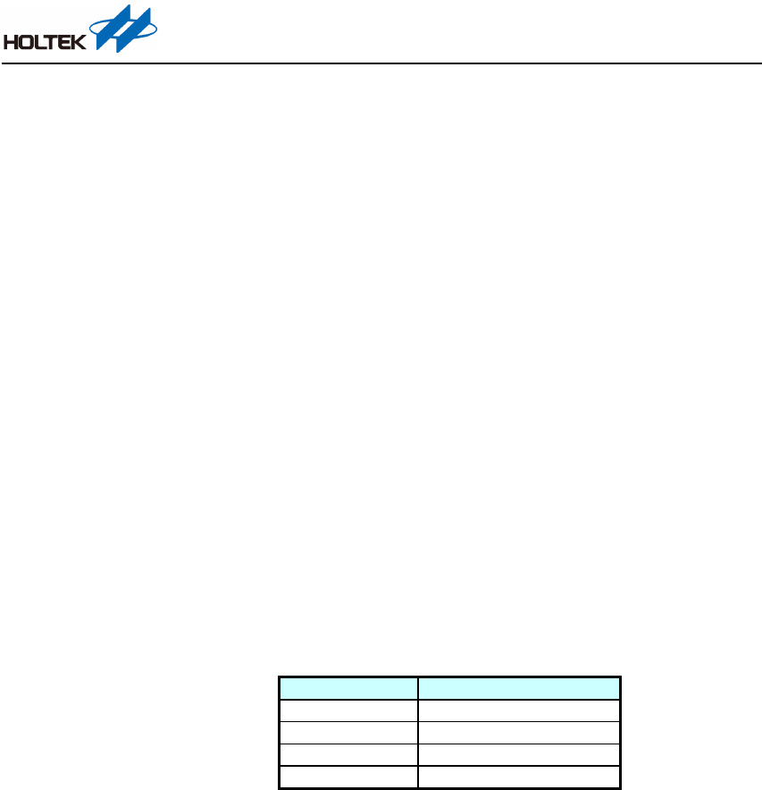
The zip file contains several folders that can be classified as Document, Firmware Library, Tools
and other items, the placement path of which is shown in Figure 5. The HT32 firmware library zip
file with a file name of HT32_STD_xxxxx_FWLib_Vm.n.r_s.zip is located under the
Firmware_Library folder.
HT32 MCU UART Application Note
AN0609EN V1.00 4 / 23 June 23, 2022
Download link: https://mcu.holtek.com.tw/ht32/resource/
Figure 5. HT32_M0p_Vyyyymmdd.zip Contents
Application Code
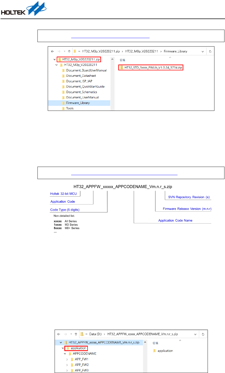
Download the application code from the following link. The application code is packaged into a zip
file with a file name of HT32_APPFW_xxxxx_APPCODENAME_Vm.n.r_s.zip. See Figure 6 for
the file name conventions.
Download link: https://mcu.holtek.com.tw/ht32/app.fw/Module_UART/
Figure 6. Application Code File Name Introduction
File and Directory Configuration
As the application code does not contain the HT32 firmware library files, the application code and
firmware library unzipped files should be placed in the correct path before starting the compilation.
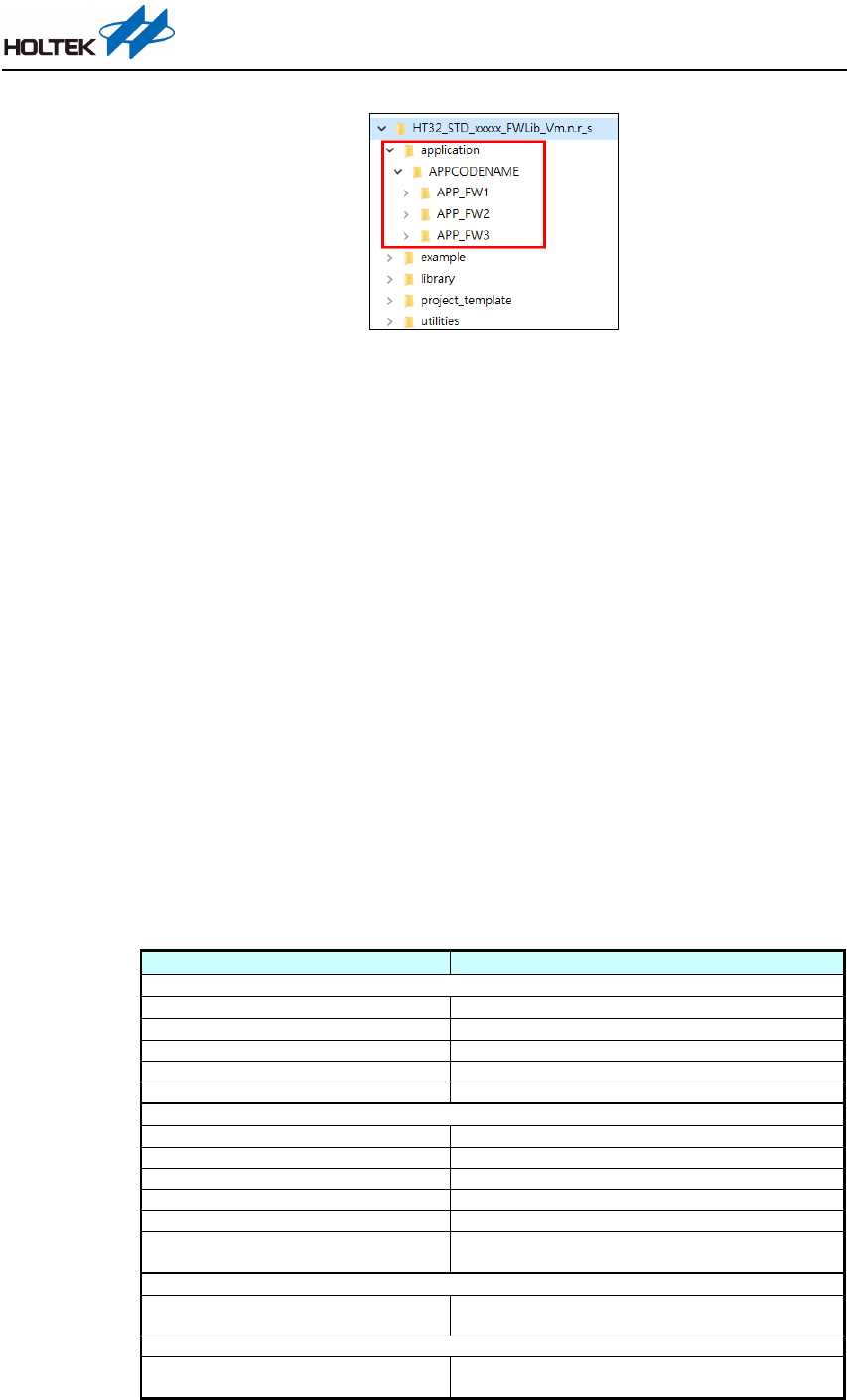
The application code zip file usually contains one or more folders, such as application and library,
as shown in Figure 7. Place the application folder under the HT32 firmware library root directory
to complete the file path configuration, as shown in Figure 8.
Alternatively, unzip the application code and HT32 firmware library simultaneously into the same
path to achieve the same configuration results.
Figure 7. HT32_APPFW_xxxxx_APPCODENAME_Vm.n.r_s.zip Contents
HT32 MCU UART Application Note
AN0609EN V1.00 5 / 23 June 23, 2022
Figure 8. Decompression Path
Terminal Software
The application code can transfer messages through the COM port to implement function selection
or status display. This requires the host side to have the terminal software installed in advance.
Users can choose appropriate connection software, or use free licensed software such as Tera Term.
In the application code, the UART channel is configured with a word length of 8-bits, no parity, 1 stop
bit and a baud rate of 115200bps.
Functional Description
This chapter will provide a functional description for the application code, including information
on the directory structure, API architecture, setting description, etc.
Directory Structure
The application code file contains an application folder. The next layer is the “Module_UART”
folder which contains two application programs, “UART_Module_Example” and “UART_Bridge”.
The relevant files are listed and described below.
Folder / File Name
Description
\\application\Module_UART\UART_Module_Example
*1
_CreateProject.bat
Batch scripts for creating project files
_ProjectSource.ini
Initialisation file for adding source code to projects
ht32_board_config.h
Setup file related to IC peripheral I/O assignment
ht32fxxxxx_01_it.c
Interrupt service program file
main.c
Main program source code
\\application\Module_UART\UART_Bridge
*2
_CreateProject.bat
Batch scripts for creating project files
_ProjectSource.ini
Initialisation file for adding source code to projects
ht32_board_config.h
Setup file related to IC peripheral I/O assignment
ht32fxxxxx_01_it.c
Interrupt service program file
main.c
Source code of the main program
uart_bridge.h
uart_bridge.c
UART bridge header file and source code file
\\utilities\middleware
uart_module.h
*3
uart_module.c
*3
API header file and source code file
\\utilities\common
ring_buffer.h
ring_buffer.c
Software ring buffer header file and source code file
Table 2. Application Code Directory Structure
HT32 MCU UART Application Note
AN0609EN V1.00 6 / 23 June 23, 2022
Note: 1. In the “UART_Module_Example” application code, the API read and write operations are
performed in a loopback manner, refer to the “API Usage Examples” section for more details.
2. In the “UART_Bridge” application code, two UART channels, UART CH0 and UART
CH1, are activated, and custom communication protocol through the COMMAND
structures are implemented between the two UART devices. For more information, refer
to the “API Usage Examples” section.
3. The application code needs to use the uart_module.c/h files which have a firmware library
version requirement. The requirement may change time to time according to the update.
To confirm the current firmware library version requirement, refer to the dependency check
content by searching for keyword “Dependency check” in the main.c file.
If the firmware library version does not meet the requirements, download the newest
version from the link provided in the “Firmware Library” section.
API Architecture
Each API has an important parameter CH, which is the UART Channel. This determines which
UART channel is to be controlled. Currently up to four UART channels are supported and therefore
four constant symbols are defined as follows. These are used as the parameter CH providing the
APIs the basis for control.
UARTM_CH0: input parameter - control or configure UART CH0
UARTM_CH1: input parameter - control or configure UART CH1
UARTM_CH2: input parameter - control or configure UART CH2
UARTM_CH3: input parameter - control or configure UART CH3
Memory space will not be wasted if only one UART channel is used. This is because the number
of the supported UART channels can be set and the unused UART channel code will be removed
by the preprocessor to increase available memory space.
The API architecture is shown in Figure 9.
API_Func ti on(CH, Buf fer)
UA RTM_CH0 UA RTM_CH1 UA RTM_CH2
UA RTM
_CH3
CH=UARTM_CH0
CH=UARTM_CH1
CH=UARTM_CH2
CH=UARTM
_CH3
CH0 S ta t us
Table
CH0_IRQ
CH1 S ta t us
Table
CH1_IRQ
CH2 S ta t us
Table
CH2_IRQ
CH3 S ta t us
Table
CH3_IRQ
CH0 HW
Parameter
CH1 HW
Parameter
CH2 HW
Parameter
CH3 HW
Parameter
h32t_board_co nfig.h
uart_module.c / h
HT_UART, HT_UART1, ...
HT_GPIO x, HT_AFIO, HT_PDMA, ...
HW
Figure 9. API Architecture Block Diagram
HT32 MCU UART Application Note
AN0609EN V1.00 7 / 23 June 23, 2022
Each API is composed of four groups of UART channel-related settings or controls so that users
only need to input the desired CH parameter. To configure the relevant API, it is only required to
have an additional UART basic configuration parameter table with the structure form,
USART_InitTypeDef. The API will implement the UART basic configuration according to the
parameter contents in the table. Refer to the “API Description” section for the UART basic
configuration structure table.
The uart_module.c/.h files only contain the interrupt (CHx_IRQ) and status table (CHx Status) of
each UART channel while all the settings required for UART communication is provided by
ht32_board_config.h. The hardware relevant parameters in the ht32_board_config.h file are shown
in the table below. More details are provided in the “Setting Description” section.
The hardware relevant parameters in the ht32_board_config.h include I/O settings and physical
UART port settings, as follows.
Symbol Description
HTCFG_UARTM_CH0 Physical UART port name; Example: UART0, UART1…
HTCFG_UARTM0_TX_GPIO_PORT Defines the port name of TX for CH0; Example: A, B, C…
HTCFG_UARTM0_TX_GPIO_PIN Defines the pin number of TX for CH0; Example: 0~15
HTCFG_UARTM0_RX_GPIO_PORT Defines the port name of RX for CH0; Example: A, B, C…
HTCFG_UARTM0_RX_GPIO_PIN Defines the pin number of TX for CH0; Example: 0~15
HTCFG_UARTM0_TX_BUFFER_SIZE Defines the TX buffer size for CH0; Example: 128
HTCFG_UARTM0_RX_BUFFER_SIZE Defines the RX buffer size for CH0; Example: 128
Table 3. Definition Symbols in ht32_board_config.h
To modify the UART channel AFIO configuration, refer to the relevant device datasheet. Currently
only the I/O definitions for UART CH0 take effect as only UART CH0 has been configured in
ht32_board_config.h. To add UART CH1~3, their I/O definitions need to be completed by referring
to the UART CH0 definition or referring to the “Setting Modification and FAQs” section.
There are three API architecture main features:
1. Up to four UART channels are supported. Their input parameters are UARTM_CH0,
UARTM_CH1, UARTM_CH2 and UARTM_CH3.
2. The number of UART channels can be set and unused channels will not reduce available
memory space.
3. All the UART settings and I/O definitions are completely separated from the APIs. This
increases the management convenience of setting values and reduces the possibility of incorrect
or missing settings.
HT32 MCU UART Application Note
AN0609EN V1.00 8 / 23 June 23, 2022
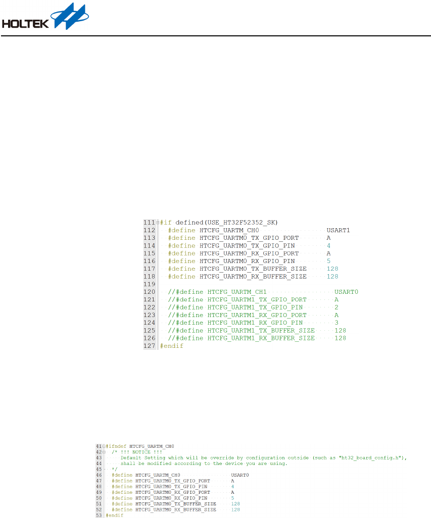
Setting Description
This section will introduce the parameter settings in the ht32_board_config.h and uart_module.h files.
1. ht32_board_config.h: This file is used for pin definitions and development board relevant
settings, which include the UART IP channel (UART0, UART1, USART0…) used by the Starter
Kit (SK), corresponding TX/RX pin locations and TX/RX buffer size. Figure 10 shows the
setting contents of the HT32F52352 Starter Kit. Depending on the functional integration of the
development, users can refer to the “Pin Assignment” section of the datasheet of the used device
to implement the pin definitions. More details about setting modification will be described in
the “Setting modification and FAQs” section.
Figure 10. ht32_board_config.h Settings (HT32F52352)
2. uart_module.h: This is the API header file used by the application code, which includes the
relevant default settings, function definitions, etc. As shown in Figure 11, the default setting
contents can be overwritten by external configurations, such as the settings in the
ht32_board_config.h file.
Figure 11. Default Settings in uart_module.h
HT32 MCU UART Application Note
AN0609EN V1.00 9 / 23 June 23, 2022
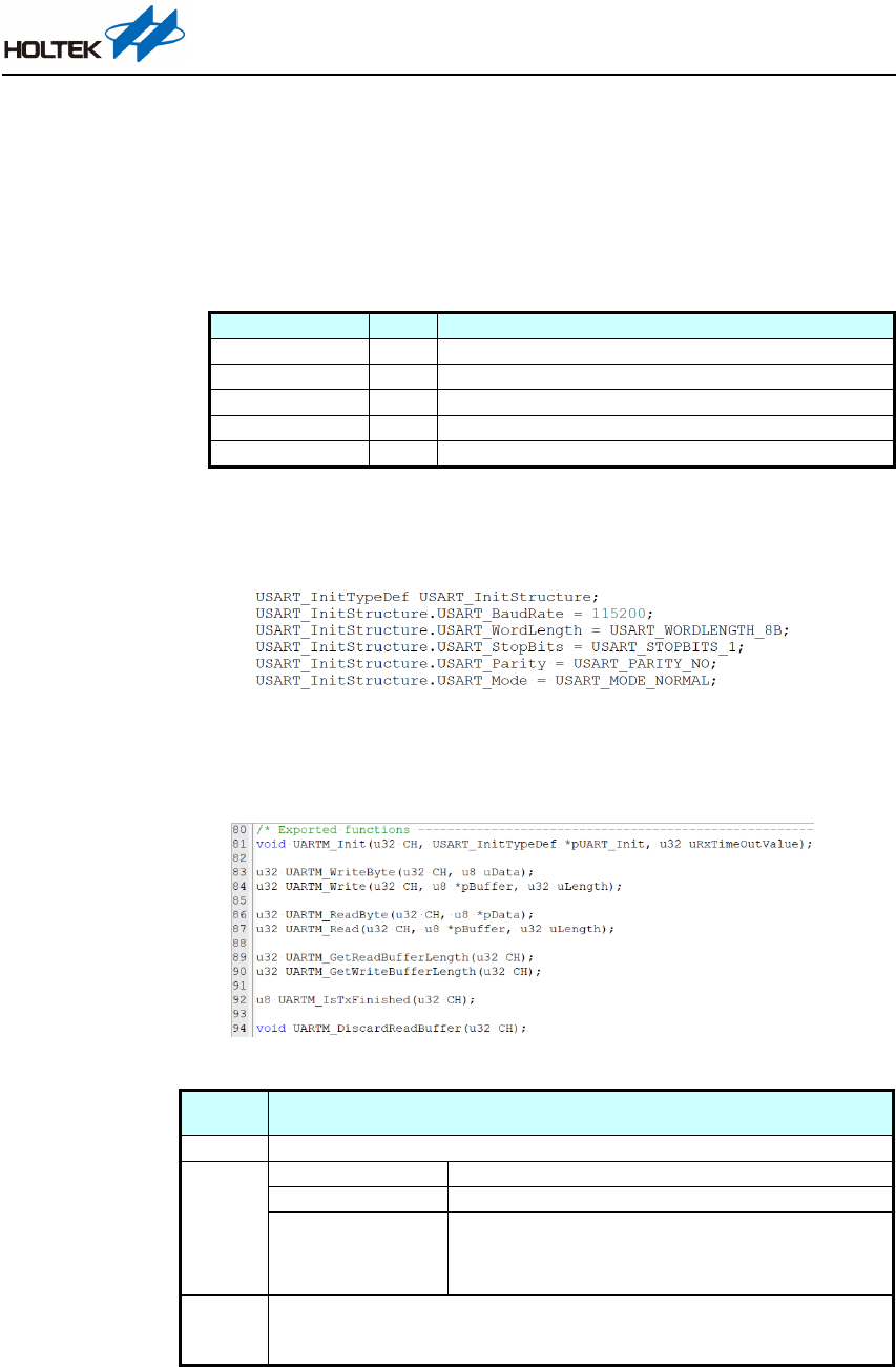
API Description
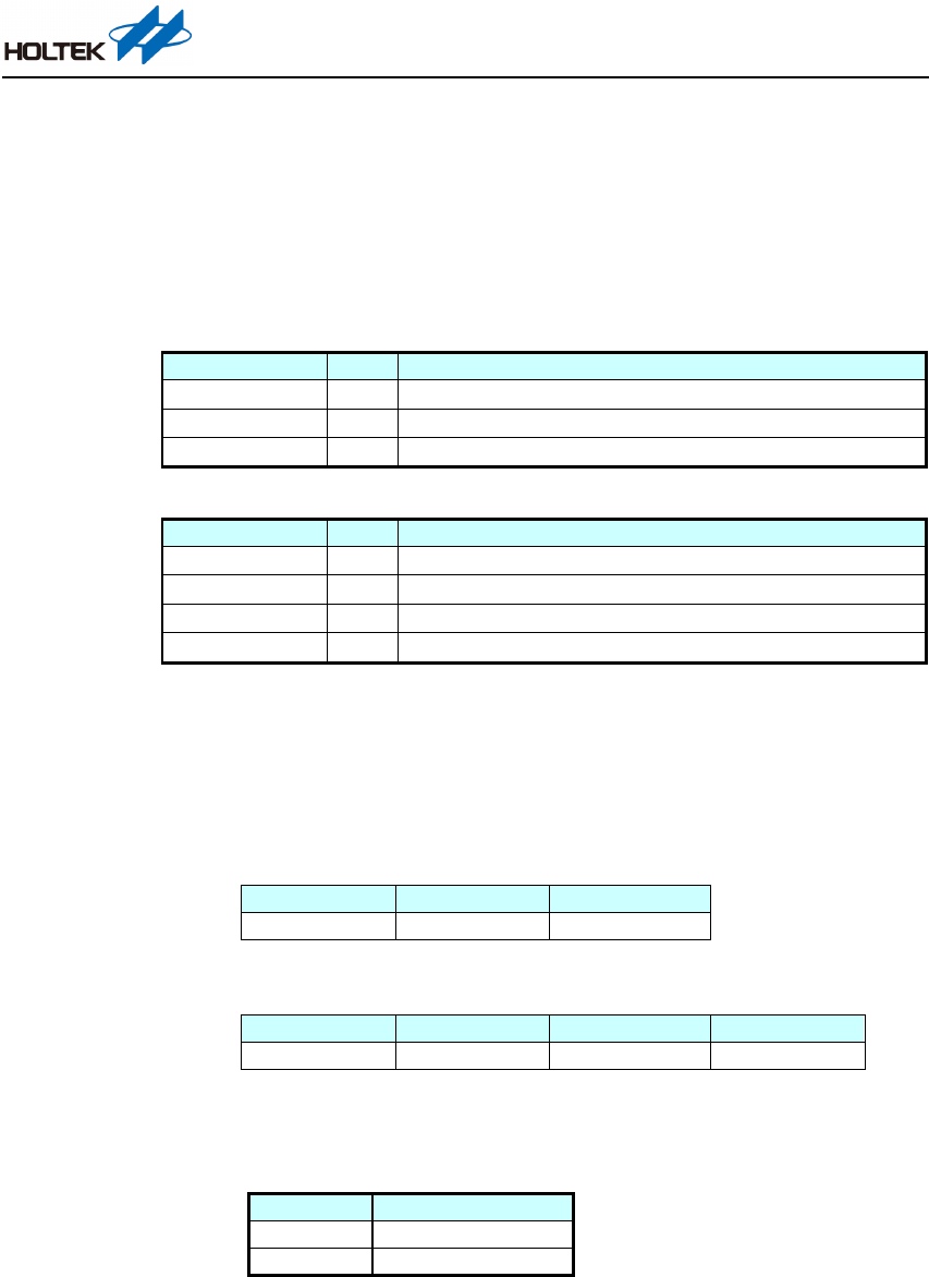
1. Application code data type description.
USART_InitTypeDef
This is the UART basic configuration structure which is composed of BaudRate,
WordLength, StopBits, Parity and Mode configurations, as shown below.
Variable Name
Type
Description
USART_BaudRate
u32
UART communication baud rate
USART_WordLength
u16
UART communication word length: 7, 8 or 9 bits
USART_StopBits
u16
UART communication stop bit length: 1 or 2 bits
USART_Parity
u16
UART communication parity: even, odd, mark, space or no parity
USART_Mode u16 UART communication mode; the APIs only support normal mode
2. Before using the API functions, complete the UART basic configuration in the main program.
The UART basic configuration for this application code is shown in Figure 12. Here the baud
rate is 115200bps, word length is 8-bit, stop bit length is 1-bit, and there is no parity.
Figure 12. UART Basic Configuration
3. Figure 13 shows the API functions declared in the uart_module.h file. The following tables
explain the function, input parameters and usage of the API functions.
Figure 13. API Function Declarations in uart_module.h
Name
void UARTM_Init(u32 CH, USART_InitTypeDef *pUART_Init, u32
uRxTimeOutValue)
Function
UART module initialisation
Input
CH
UART channel
pUART_Init UART basic configuration structure pointer
uRxTimeOutValue
UART RX FIFO time-out value. When the RX FIFO
receives
new data the counter will reset and restart. Once the counter
reaches the preset time-out value and the corresponding time-
out
interrupt has been enabled, a time-out interrupt will be generated.
Usage
UARTM_Init(UARTM_CH0, &USART_InitStructure, 40);
//Execute UART basic configuration
//Refer to Figure 12 for USART_InitStructure configuration
HT32 MCU UART Application Note
AN0609EN V1.00 10 / 23 June 23, 2022
Name
u32 UARTM_WriteByte(u32 CH, u8 uData)
Function
UART module write byte operation (TX)
Input
CH
UART channel
uData
The data to be written
Output
SUCCESS
Successful
ERROR
Failed
Usage
UARTM_WriteByte(UARTM_CH0, 'A'); //UART writes 1 byte - 'A'
Name
u32 UARTM_Write(u32 CH, u8 *pBuffer, u32 uLength)
Function
UART module write operation (TX)
Input
CH
UART channel
pBuffer Buffer pointer
uLength
The length of the data to be written
Output
SUCCESS
Successful
ERROR
Failed
Usage
u8 Test[] = "This is test!\r\n";
UARTM_Write(UARTM_CH0, Test, sizeof(Test) -1); //UART writes pBuffer data
Name
u32 UARTM_ReadByte(u32 CH, u8 *pData)
Function
UART module read byte operation (RX)
Input
CH
UART channel
pData
The address to place the read data
Output
SUCCESS
Successful
ERROR
Failed (no data)
Usage
u8 TempData;
if (UARTM_ReadByte(UARTM_CH0, &TempData) == SUCCESS)
{
UARTM_WriteByte(UARTM_CH0, TempData);
}
//If UARTM_ReadByte() returns SUCCESS then UART writes this data byte
Name
u32 UARTM_Read(u32 CH, u8 *pBuffer, u32 uLength)
Function
UART module read operation (RX)
Input
CH
UART channel
pBuffer
Buffer pointer
uLength
The length of the data to be read
Output
Read count
The length of the data has been read
Usage
u8 Test2[10];
u32 Len;
Len = UARTM_Read(UARTM_CH0, Test2, 5);
if (Len > 0)
{
UARTM_Write(UARTM_CH0, Test2, Len);
}
//UARTM_Read() reads 5 bytes of data and stores data into Test2, and assigns the read
byte count to Len
//Write the data sourced from Test2
HT32 MCU UART Application Note
AN0609EN V1.00 11 / 23 June 23, 2022
Name
u32 UARTM_GetReadBufferLength(u32 CH)
Function
Obtain the read buffer length (RX)
Input
CH
UART channel
Output
uLength
Read buffer length
Usage
UARTM_Init(UARTM_CH0, &USART_InitStructure, 40); //UART module initialisation
while (UARTM_GetReadBufferLength(UARTM_CH0) < 5);
//Wait until UARTM_ReadBuffer has received 5 bytes of data
Name
u32 UARTM_GetWriteBufferLength(u32 CH)
Function
Obtain the write buffer length (TX)
Input
CH
UART channel
Output
uLength
Write buffer length
Name
u8 UARTM_IsTxFinished(u32 CH)
Function
Obtain the TX status
Input
CH
UART channel
Output
TRUE
TX status: finished
FALSE TX status: not finished
Usage
UARTM_WriteByte(UARTM_CH0, 'O');
#if 1 // "uart_module.c" SVN >= 525 required
while (UARTM_IsTxFinished(UARTM_CH0) == FALSE)
#else
while (1)
#endif
//This API can be used to check the TX status, as shown above; wait until the
UARTM_WriteByte() API has finished, i.e., TX status is TRUE,
and then continue the
subsequent actions.
//A restriction is added because this function has not been added until the SVN version
number in uart_module.c is 525.
Name
void UARTM_DiscardReadBuffer(u32 CH)
Function
Discard the data in the read buffer
Input
CH
UART channel
API Usage Examples
This section will demonstrate API write and read examples of the “Module_UART” application
code using the initialisation process and the “UART_Module_Example” application code process.
Before using the APIs, users need to include the API header file into the main program source code
file (#include "middleware/uart_module.h").
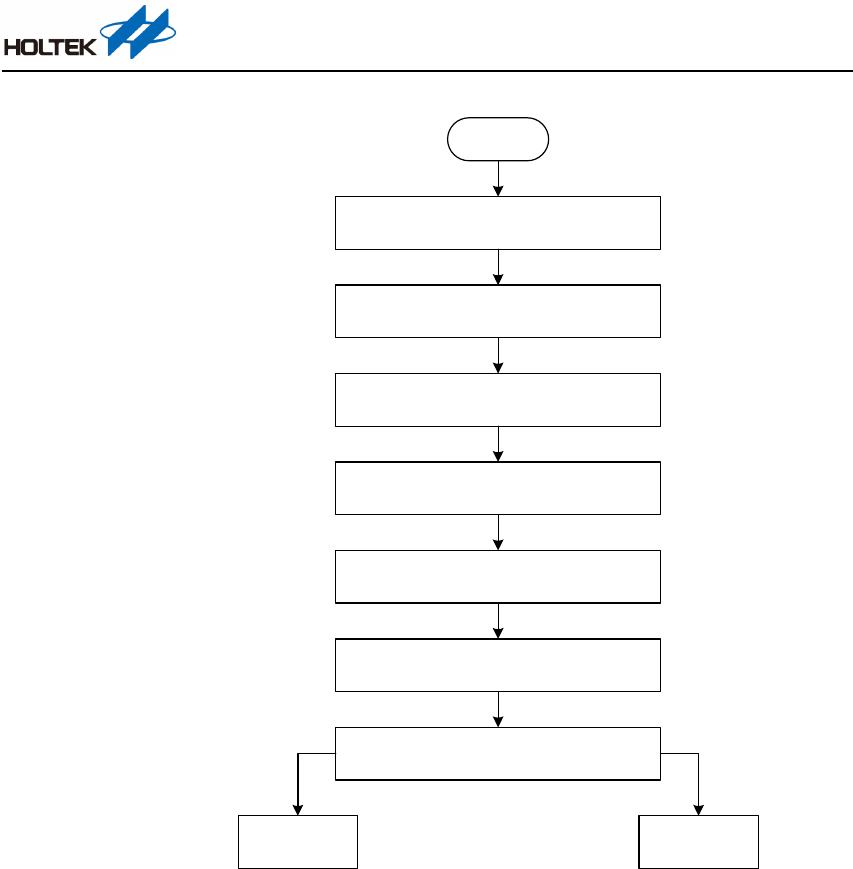
As shown in Figure 14, when entering the initialisation process, first define the UART basic
configuration structure. Then configure the UART basic configuration structure members including
BaudRate, WordLength, StopBits, Parity and Mode. Finally, call the API initialisation function, the
completion of which indicates the end of the initialisation process. After this users can continue the
write and read operations based on the preset UART basic configuration.
HT32 MCU UART Application Note
AN0609EN V1.00 12 / 23 June 23, 2022
Start
UART basic configuration structur e definition:
USART_InitTypeDef USART_InitStructure
Set UART communication baud rate:
USART_InitStructure.USART_BaudRate = xxxx
Set UART communication word length:
USART_InitStructure.USART_WordLength = xxxx
Set the number of UART communication stop bits:
USART_InitStructure.USART_Sto pBits = xxxx
Set UART communication parity:
USART_InitStructure.USART_Parity = xxxx
Set UART communication mode:
USART_InitStructure.USART_Mode = xxxx
Call UART API initialisation function:
UARTM_Init(UARTM_CH0, &USART_InitStructure, 40)
UART write process UART read process
Figure 14. Initialisation Flowchart
HT32 MCU UART Application Note
AN0609EN V1.00 13 / 23 June 23, 2022
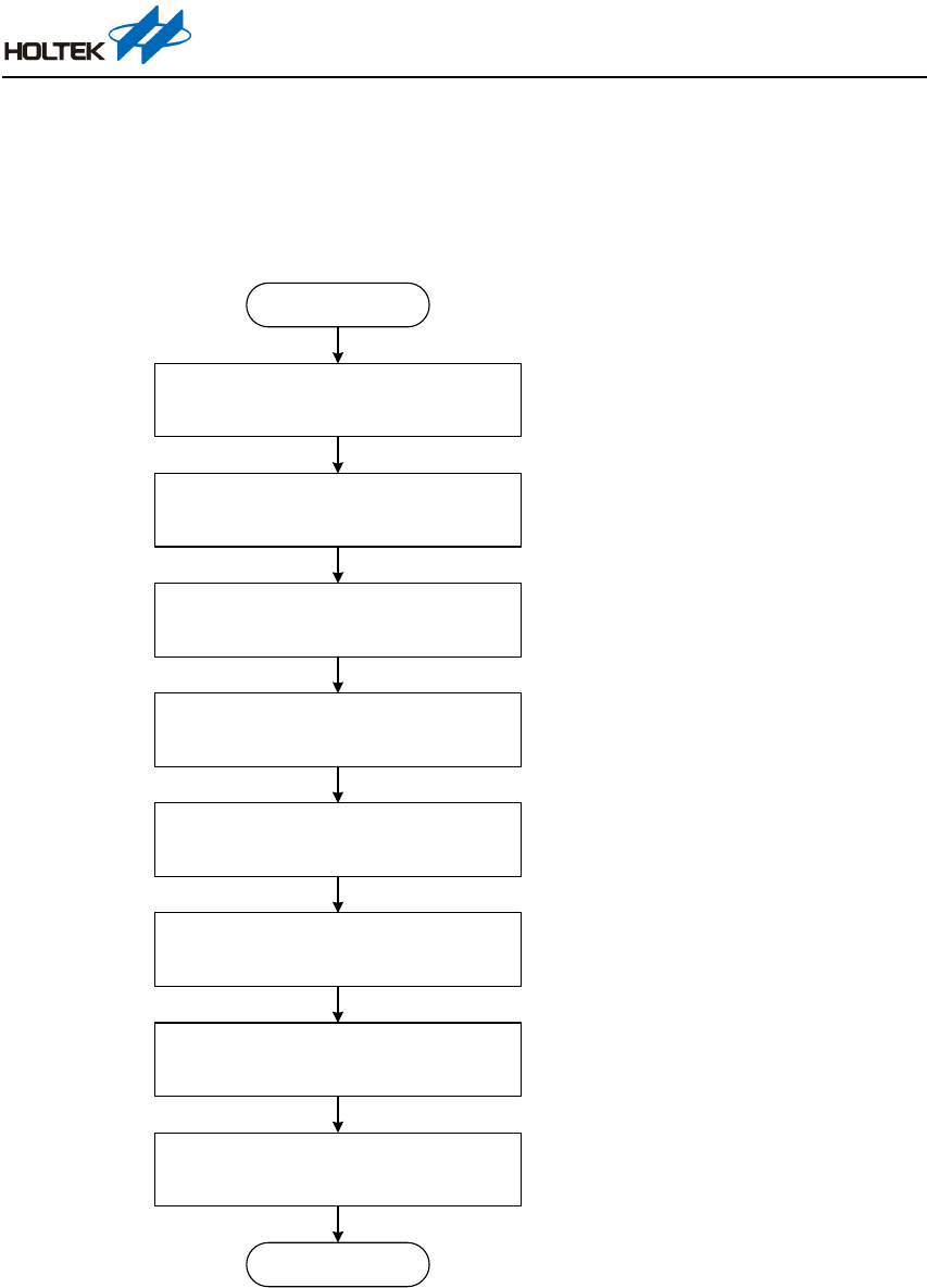
The “UART_Module_Example” application code demonstrates the API read and write operations
in a loopback manner. The flowchart for this is shown in Figure 15. The API functions used include
UARTM_WriteByte(), UARTM_Write(), UARTM_ReadByte(), UARTM_Read() and
UARTM_GetReadBufferLength(). Their description are provided in the “API Description” section.
Write & Read Operations
Start
Set related parameters
UARTM
_WriteByte( ): UART write byte operations
UARTM
_W rite ( ): UART write operation of specified length
UARTM_GetReadBufferLength( ),
wait until 5 bytes of data have been received
UARTM_ReadByte( ) reads the first byte;
if successful, UARTM_WriteByte
( )
writes the read byte
UARTM_ReadByte( ) reads the second byte;
if successful, UARTM_WriteByte( ) writes the read byte
UARTM_Read( ) reads 10 bytes of data and stores data into
Test2, then assigns the returned read byte count to Len
UARTM_W rite( ) writes the specified length of data
derived from Test2
Write
& Read Operations
End
u8 Test[] = "This is test!\r\n";
u8 Test2[10];
u8 TempData;
u32 Len;
UARTM_WriteByte(UARTM_CH0, 'A');
UARTM_WriteByte(UARTM_CH0, 'B');
UARTM_WriteByte(UARTM_CH0, 'C');
UARTM_W rite(UARTM _CH0, Test, sizeof(Test) -1);
while (UARTM_GetReadBufferLength(UARTM_CH0) < 5);
if (U ARTM_ReadByte(UARTM
_CH0, &
TempData) ==
SUCCESS)
{
UARTM _WriteByte(UARTM_
CH0, TempData
);
}
if (U ARTM_ReadByte(UARTM_CH0, &TempData) == SUCCESS)
{
UARTM _WriteByte(UARTM_
CH0, TempData
);
}
Len = UARTM_Read(UARTM_CH0, Test2, 10);
if (Len > 0)
{
UARTM _W rite(UARTM_CH0, Test2, Len);
}
Figure 15. Flowchart of Write and Read Examples
HT32 MCU UART Application Note
AN0609EN V1.00 14 / 23 June 23, 2022
There is another “UART_Bridge” application code under the “Module_UART” folder whose
related file description is introduced in the “Directory Structure” section.
The “UART_Bridge” application code activates two UART channels, UART CH0 and UART CH1,
and then customises the communication protocol between the two UART devices through
COMMAND structures, gCMD1 and gCMD2. These are defined in uart_bridge.c, as shown below.
UARTBridge_CMD1TypeDef gCMD1:
Variable Name
Type
Description
uHeader
u8
Header
uCmd
u8
Command
uData[3]
u8
Data
UARTBridge_CMD2TypeDef gCMD2:
Variable Name
Type
Description
uHeader
u8
Header
uCmdA
u8
Command A
uCmdB
u8
Command B
uData[3]
u8
Data
In the “UART_Bridge” application code, use gCMD1 to receive data as a command packet and then
analyse it. Then according to the customised communication protocol, set gCMD2 as a response
packet and transmit it. The following is an example of a command packet (gCMD1) and a response
packet (gCMD2).
Command Packet (UARTBridge_CMD1TypeDef gCMD1):
Byte 0
Byte 1
Byte 2 ~ Byte 4
uHeader
uCmd
uData [3]
“A”
“1”
“x, y, z”
Response Packet (UARTBridge_CMD2TypeDef gCMD2):
Byte 0
Byte 1
Byte 2
Byte 3 ~ Byte 5
uHeader
uCmdA
uCmdB
uData [3]
“B”
“a”
“1”
“x, y, z”
Resource Occupation
Taking the HT32F52352 as an example, the resources occupied by the UART module is shown below.
HT32F52352
ROM Size
946 Bytes
RAM Size
40
*1
+ 256
*2
Bytes
Note: 1. Global variables including flags and status for a single channel occupy 40 bytes of RAM.
2. This is for a condition where a single channel is used and the TX/RX buffer size is 128/128
bytes. The buffer size can be set according to the application requirements.
Table 4. Application Code Resource Occupation
Compilation environment: MDK-Arm V5.36, ARMCC V5.06 update 7 (build 960)
Optimise option: Level 2 (-O2)
HT32 MCU UART Application Note
AN0609EN V1.00 15 / 23 June 23, 2022
Instructions for Use
This chapter will introduce the environmental preparation for the “Module_UART” application
code, as well as the compilation and test steps.
Environmental Preparation
The hardware and software required for the “Module_UART” application code are listed below.
Hardware/Software
Count
Note
Starter Kit
1
This application note uses the HT32F52352 Starter Kit as an example
USB Cable
1
Micro USB, connected to PC
Application Code —
The download path, file and directory configuration are introduced in the
“Resource Download and Preparation” section.
Path: “\\application\Module_UART\UART_Module_Example”
Tera Term
—
Refer to the “Terminal Software” section
Keil IDE
—
Keil uVision V5.xx
Table 5. Hardware/Software Environmental Preparation
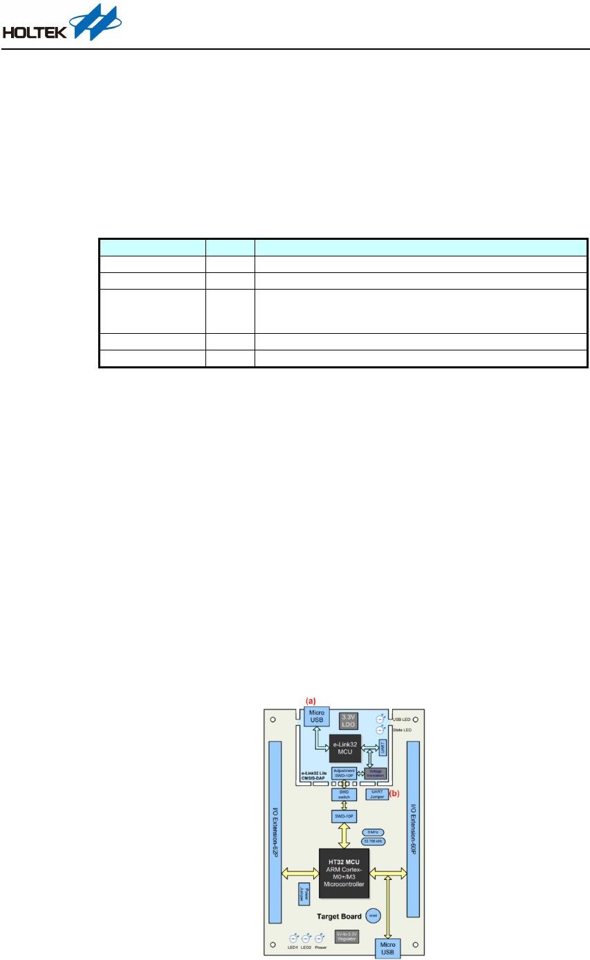
First, use the HT32F52352 Starter Kit combined with the Virtual COM Port (VCP) function of
e-Link32 Lite for the UART application introduction. This requires the following environmental
preparation to be implemented:
(1) There are two USB interfaces on the board. Use the USB cable to connect the PC and the e-
Link32 Lite interface on the board as shown in Figure 16-(a).
(2) As the application code needs to use the e-Link32 Lite Virtual COM Port (VCP) function, ensure
that the PAx
*2
and DAP_Tx of UART Jumper-J2
*1
has been shorted using a jumper. The J2
location is indicated by Figure 16-(b).
Note: 1. J2 on the Starter Kit has two options, PAx and DAP_Tx shorted or PAx and RS232_Tx
shorted. Refer to the Starter Kit user manual for the detailed setting functions.
2. The MCU UART RX pin location on different Starter Kits are different. This example
uses PAx to indicate the RX pin.
Figure 16. HT32 Starter Kit Block Diagram
HT32 MCU UART Application Note
AN0609EN V1.00 16 / 23 June 23, 2022
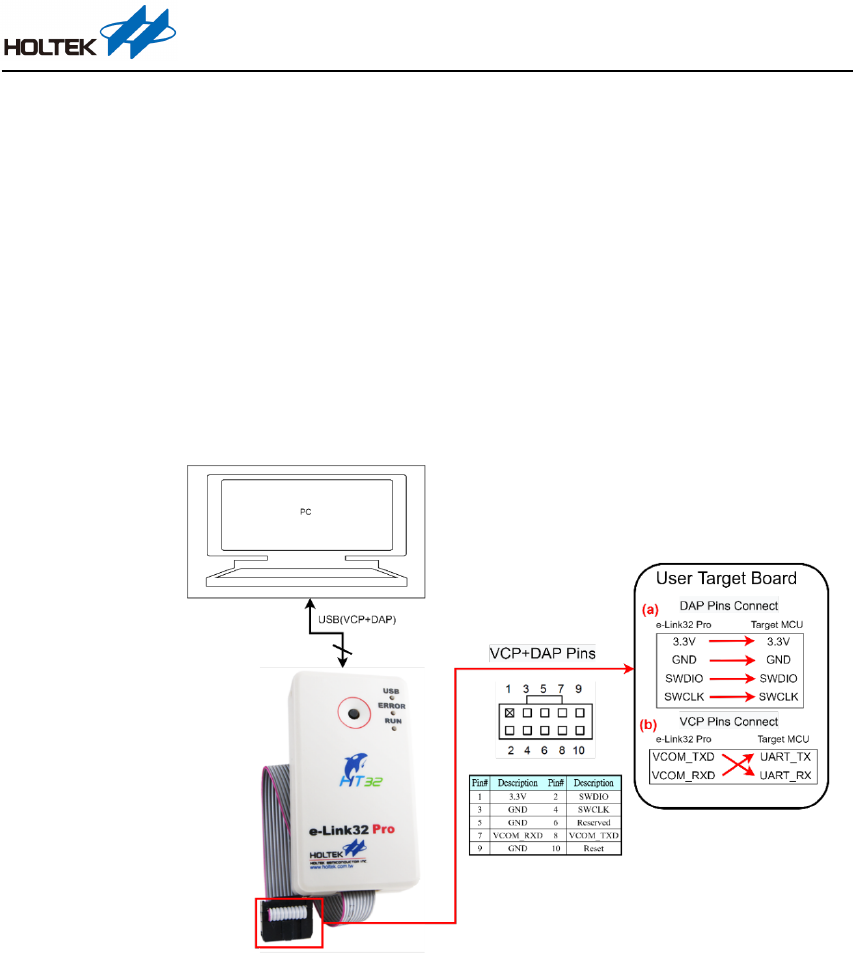
Now use the user target board combined with the Virtual COM Port (VCP) function of the e-Link32
Pro for the UART application introduction. This requires the following environmental preparation
to be implemented:
(1) One side of e-Link32 Pro is connected to a PC using a Mini USB cable and the other side is
connected to the user target board through its 10-bit grey cable. The connection between the
SWD interfaces of the cable and target board is implemented using Dupont lines, as shown in
Figure 17-(a).
(2) The serial communication pins of the e-Link32 Pro are Pin#7-VCOM_RXD and Pin#8-
VCOM_TXD. These should be connected to the TX and RX pins of the user target board, as
shown in Figure 17-(b).
Figure 17. e-Link32 Pro + User Target Board Block Diagram
Compilation and Test
This section will take the “application\Module_UART\UART_Module_Example” as an example
to introduce the compilation and test processes. Before this, ensure that all the preparations
described in the previous section have been implemented and that the Tera Term terminal software
has been downloaded.
The detailed operation steps are summarised below.
Step 1. Power-on test
Set up the hardware environment as described in the previous section. After power-on, the
D9 power LED on the lower left of the Starter Kit will be illuminated. The D1 USB LED
on the e-Link32 Lite on the upper right will be illuminated after the USB enumeration has
completed. If D1 is not illuminated after a long period of time, confirm whether the USB
cable is able to communicate. If not then remove it and re-insert it again.
HT32 MCU UART Application Note
AN0609EN V1.00 17 / 23 June 23, 2022
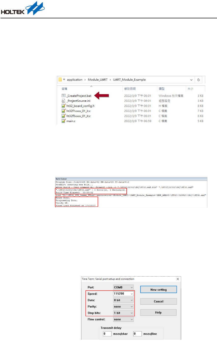
Step 2. Generate a project
Open the application\Module_UART\UART_Module_Example folder, click on the
_CreateProject.bat file to generate a project, as shown in Figure 18. Since this application
note uses the HT32F52352 Starter Kit, open the Keil IDE project “Project_52352.uvprojx”
located under the MDK_ARMv5 folder.
Figure 18. Execute _CreateProject.bat to Generate Project
Step 3. Compile and program
After the project has been opened, first click on “Build” (or use shortcut “F7”), then click
on “Download” (or use shortcut “F8”). After this, the build and download results will be
displayed in the Build Output window. See Figure 19.
Figure 19. Build and Download Results
Step 4. Open the Tera Term software and configure the serial port
Open the Tera Term software and the COM port. Pay attention to whether the COM port
number generated by the Starter Kit is correct or not. Then click on “Setup >> Serial Port”
to enter the configuration interface. The UART interface configuration of the
“Module_UART” application code is described in the “Terminal Software” section. The
setup result is shown in Figure 20.
Figure 20. Tera Ter m Serial Port Setup Result
HT32 MCU UART Application Note
AN0609EN V1.00 18 / 23 June 23, 2022
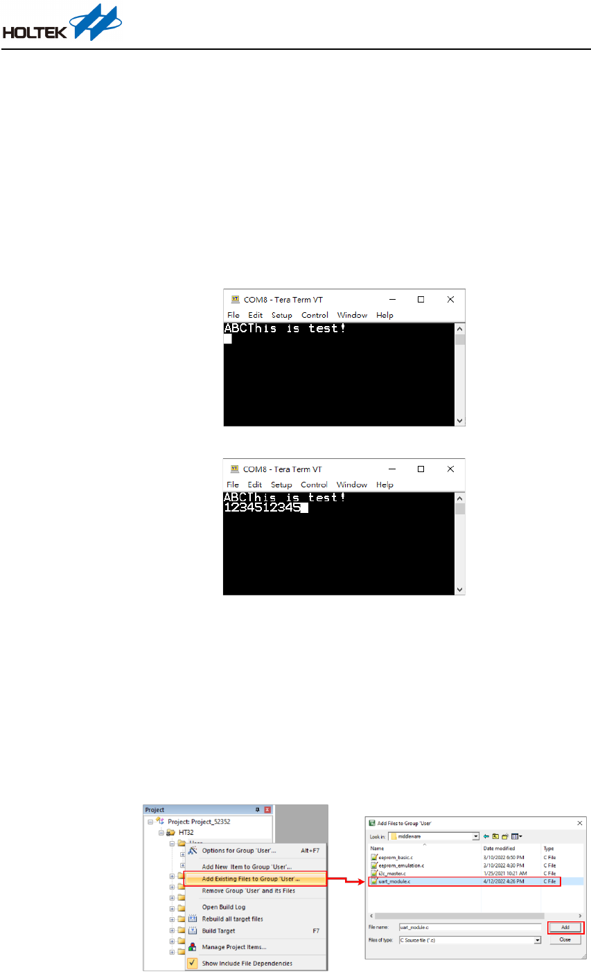
Step 5. Reset the system and test
Press the SK reset key – B1 Reset. After this, a “ABCThis is test!” message will be
transmitted through the API and will be displayed in the Tera Term window, as shown in
Figure 21. Regarding the receive function, when entering data into the Tera Term window,
the relevant API will be used to determine the receive buffer length. When the data received
by PC reaches 5 bytes, the received 5 bytes of data will be sent out sequentially. As shown
in Figure 22, the data sequentially entered is “1, 2, 3, 4, 5”, which is received and
determined through the API. After this, the data “1, 2, 3, 4, 5” will be printed after the five
inputs.
Figure 21. “Module_UART” Application Code Functional Test – Transmit
Figure 22. “Module_UART” Application Code Functional Test – Receive
Transplant Instructions
This section will introduce how to integrate the APIs into the user’s projects.
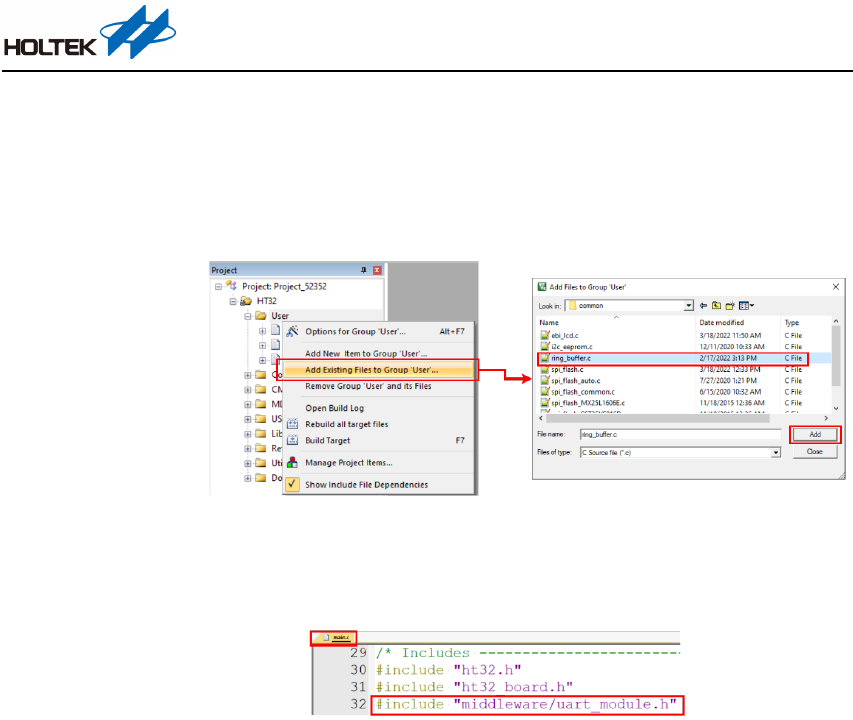
Step 1. Add the uart_module.c file into the project. Right-click on the User folder. Select “Add
Existing Files to Group ‘User’…”, then select the uart_module.c file and click on “Add”,
as shown in Figure 23.
Refer to the “Directory Structure” section for the file path description.
Figure 23. Add uart_module.c File to Project
HT32 MCU UART Application Note
AN0609EN V1.00 19 / 23 June 23, 2022
Step 2. Add the ring_buffer.c file into the project. Right-click on the User folder. Select “Add
Existing Files to Group ‘User’…”, then select the ring_buffer.c file and click on “Add”, as
shown in Figure 24.
Refer to the “Directory Structure” section for the file path description.
Figure 24. Add ring_buffer.c File to Project
Step 3. Include the API header file into the beginning of main.c, as shown in Figure 25.
(Ext: #include
"middleware/uart_module.h")
Figure 25. Include API Header File to main.c
Step 4. Implement the settings required for the UART communication using the ht32_board_config.h
file. This is introduced in detail in the “Setting Description” and “Setting Modification and
FAQs” sections.
Setting Modification and FAQs
This section will introduce how to modify the UART settings and explain some common questions
encountered during use.
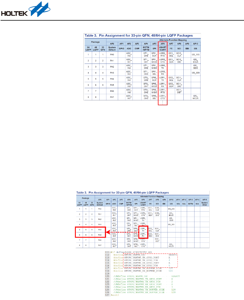
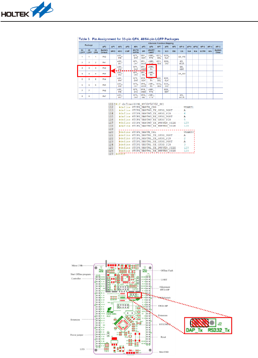
Change UART Pin Assignment
Taking the HT32F52352 HTCFG_UARTM_CH0 as an example, here it is described how to change
the UART pin definitions.
1. Referring to the HT32F52352 Datasheet “Pin Assignment” chapter, look up the Alternate
Function Mapping table which lists the AFIO functions of the device type. For the UART
relevant pins, refer to the “AF6 USART/UART” column, as shown in Figure 26.
HT32 MCU UART Application Note
AN0609EN V1.00 20 / 23 June 23, 2022
Figure 26. HT32F52352 Alternate Function Mapping Table
2. This step will guide users to locate the corresponding UART pins using the above table. The
HT32F52352 example uses USART1 as the default channel. Here, the TX and RX pins are
USR1_TX and USR1_RX and are located on PA4 and PA5 respectively. Figure 27 shows the
pin correspondence as well as the pin definitions in “ht32_board_config.h”. The empty fields
of “Package” in the pin assignment table means that there are no relevant GPIOs in this package.
To modify the UART pins, find the target pin locations and re-define the pins using the
“ht32_board_config.h” file.
Figure 27. Pin Correspondence and Setting Modification
Add a UART Channel
Taking the HT32F52352 HTCFG_UARTM_CH1 as an example, here it is described how to add a
new UART channel.
Modify the ht32_board_config.h file
Referring to the HT32F52352 Datasheet “Pin Assignment” chapter, look up the Alternate
Function Mapping table which lists the AFIO functions of the device type. As USART1 has
been used as HTCFG_UARTM_CH0, the newly added HTCFG_UARTM_CH1 can choose
USART0. Here, the TX and RX pins are located on PA2 and PA3 respectively, as shown in the
upper half of Figure 28. The corresponding modifications are implemented using code lines
120~126 in ht32_board_config.h, as shown by the red dotted box in Figure 28.
HT32 MCU UART Application Note
AN0609EN V1.00 21 / 23 June 23, 2022
Figure 28. Add a UART Channel
FAQs
Q: In step 5 of the Compilation and Test section, the transmit functional test is normal. Here, the
“ABCThis is test!” message has been displayed successfully, however for the receive function,
why the five input values are not returned and displayed?
A: Check whether the MCU UART RX and DAP_Tx pins of UART Jumper-J2 have been shorted
using a jumper. As the “Module_UART” application code needs to use the Virtual COM Port
(VCP) of e-Link32 Lite, the short-circuit setting should be applied to the left two pins of UART
Jumper-J2, as shown in Figure 29.
Figure 29. UART Jumper-J2 Setting
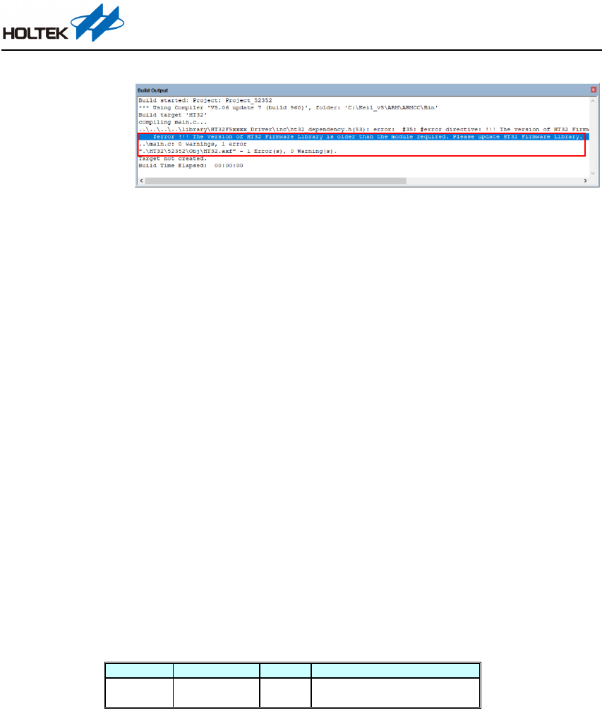
Q: After executing “Build”(or shortcut “F7”), an error message appears indicating that the firmware
library version is older than the one that is required? See Figure 30.
A: The implementation of the “Module_UART” application code needs to include the uart_module.c/h
files which has a requirement for a certain firmware library version. When such an error message
appears, it means the currently used firmware library is an older version. Therefore it is necessary
to download the newest version through the link provided in the “Firmware Library” section.
HT32 MCU UART Application Note
AN0609EN V1.00 22 / 23 June 23, 2022
Figure 30. Firmware Library Version Error Message
Conclusion
This document has provided a basic introduction to assist users with a better understanding of the
“Module_UART” application code and UART communication protocol. This was followed by the
resource download and preparation. The Functional Description chapter introduced the file
directory structure, the API architecture, API description and API usage examples. The Instructions
for Use chapter demonstrated the environmental preparation, compilation and testing of the
“Module_UART” application code. It also provided instructions for code transplant and
modification setting as well as explaining some common problems that may be encountered. All
of this combined will allow users to quickly understand how to use the APIs and subsequently
reduce the amount of time to get started.
Reference Material
For more information, refer to the Holtek website: www.holtek.com
Versions and Modification Information
Date
Author
Release
Modification Information
2022.04.30
蔡期育
(Chi-Yu Tsa i )
V1.00 First Version

HT32 MCU UART Application Note
AN0609EN V1.00 23 / 23 June 23, 2022
Disclaimer
All information, trademarks, logos, graphics, videos, audio clips, links and other items appearing
on this website ('Information') are for reference only and is subject to change at any time without
prior notice and at the discretion of Holtek Semiconductor Inc. and its related companies
(hereinafter 'Holtek', 'the company', 'us', 'we' or 'our'). Whilst Holtek endeavors to ensure the
accuracy of the Information on this website, no express or implied warranty is given by Holtek to
the accuracy of the Information. Holtek shall bear no responsibility for any incorrectness or leakage.
Holtek shall not be liable for any damages (including but not limited to computer virus, system
problems or data loss) whatsoever arising in using or in connection with the use of this website by
any party. There may be links in this area, which allow you to visit the websites of other companies.
These websites are not controlled by Holtek. Holtek will bear no responsibility and no guarantee to
whatsoever Information displayed at such sites. Hyperlinks to other websites are at your own risk.
Limitation of Liability
In no event shall Holtek Limited be liable to any other party for any loss or damage whatsoever or
howsoever caused directly or indirectly in connection with your access to or use of this website, the
content thereon or any goods, materials or services.
Governing Law
The Disclaimer contained in the website shall be governed by and interpreted in accordance with
the laws of the Republic of China. Users will submit to the non-exclusive jurisdiction of the
Republic of China courts.
Update of Disclaimer
Holtek reserves the right to update the Disclaimer at any time with or without prior notice, all
changes are effective immediately upon posting to the website.
